Hi Pierre,
Could you upload your input/output files for cross-checking? And and relevant fort files that contain some errors.
Cheers,
Aleks
Aleksandar Zivkovic
Posts
-
fort.62 issue -
SCANMODE problemEither way, seems you got your geometry for further optimization

Cheers,
A -
SCANMODE problemDear Jonas,
The basis set linear dependence issue might arise from the fact that the geometry in the scan step changes too much from the starting point and hence the interatomic distance changes a lot. Your scan step seems rather large, maybe that is the underlying issue. You can print out the geometry that will be scanned (by setting the first number as a negative values, i.e., "-1") and check that it is sensible. But perhaps I would first try with the smaller step, say 0.4 as in the first case and see if that helps.
Cheers,
Aleks -
SCANMODE problemDear Jonas,
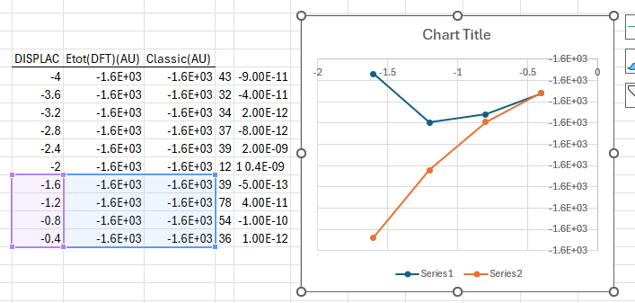
I took your provided data and plotted it. At first, it indeed seems as monotonically decreasing along one side of the quadratic function, but if you zoom in closely, you will notice this little "drop":
.I suggest you do a second scanning along the same vibrational mode, but on a finer grid (e.g., step of 0.05) in the interval -1.6 / +1.6. Then take the geometry from one of the local minima (to the left and to the right of the central point, they need to be equivalent) and optimise it. The subsequent frequencies should be positive, unless there is a second negative mode or your structure is intrinsically unstable at these conditions.
Hope this helps.
Cheers,
Aleks -
SCF fails spinlock with POB-DZVP-REV2Hi,
Have you tried running a calculation where you specify the full basis set via the general route? This way one could rule out whether the internally stored basis set has some intrinsic error associated with it.
You also have DIIS turned on, which can cause issues with spin locking and cause instabilities. You can try switching it off (NODIIS) or alternatively remove spin lock, set up the spins at the beginning (ATOMSPIN) and monitor whether the DIIS is keeping the right solution.
Still might be a bug, but worth ruling out the simpler possibilities.
Hope it helps.
Cheers,
Aleks -
Problem with Restart in MPPcrystalDear Rams,
From your input/output files, it doesn't seem you are doing anything particularly wrong. It is more that the system is perhaps a bit more challenging. Here are a few ideas that might be of use regarding speed up and convergence:
i) You are having quite large lattice parameters (15 Angstrom in each direction). In this case having a 4x4x4 mesh of k-points is perhaps even more than needed to converge the total energy, so you can try reducing it to a 3x3x3 or 2x2x2 mesh to reduce the computational cost and get some speed up (without compromising quality). You could probably go to 1 k-point just as well, but then you might not get a correct Fermi level sampled. Which brings me to the second point...
ii) Do you expect your system to be metallic? If so, you can test a few values of the smearing parameter to see whether it makes a difference to the convergence behaviour. If you know you need to get a semiconductor, then you might want to try shifting the occupied states down in energy (keyword LEVSHIFT to prevent the system from getting stuck in a conducting state and causing the SCF to get stuck...
iii) You have the DIISALLK keyword in your input file, have you tested that as necessary for the convergence of the undoped cell? It does increase the memory/storage requirements, so could be worth trying with just the default (gamma-point) DIIS...
iv) One alternative is to turn off the DIIS convergence accelerator and revert to "classical" Fock mixing. Albeit slower in convergence than DIIS, it can stabilize the SCF procedure avoiding strong, sudden oscillation in the solution (while DIIS is turned on, the FMIXING is used only in the very first SCF step)...
v) Coming back to the charge oscillations you observed, they do indeed start appearing very quickly in your second run.
Here are the corresponding total energies from your OUTPUT_Run1.d12:CYC 0 ETOT(AU) -1.128999989618E+05 DETOT -1.13E+05 tst 0.00E+00 PX 1.00E+00 CYC 1 ETOT(AU) -1.129553711002E+05 DETOT -5.54E+01 tst 0.00E+00 PX 1.00E+00 CYC 2 ETOT(AU) -1.129699205883E+05 DETOT -1.45E+01 tst 7.60E-05 PX 9.78E-02 CYC 3 ETOT(AU) -1.123277877060E+05 DETOT 6.42E+02 tst 4.05E+00 PX 8.33E+00 CYC 4 ETOT(AU) -1.123934069238E+05 DETOT -6.56E+01 tst 1.68E-01 PX 6.66E+00 CYC 5 ETOT(AU) -1.128505608381E+05 DETOT -4.57E+02 tst 2.53E-01 PX 1.17E+00 CYC 6 ETOT(AU) -1.126570396187E+05 DETOT 1.94E+02 tst 1.41E-01 PX 1.13E+00 CYC 7 ETOT(AU) -1.129397986733E+05 DETOT -2.83E+02 tst 1.36E-01 PX 1.16E+00 CYC 8 ETOT(AU) -1.128184205493E+05 DETOT 1.21E+02 tst 9.81E-02 PX 6.95E-01 CYC 9 ETOT(AU) -1.129501102455E+05 DETOT -1.32E+02 tst 9.49E-02 PX 6.74E-01 CYC 10 ETOT(AU) -1.129223250516E+05 DETOT 2.78E+01 tst 5.80E-01 PX 6.62E-01And then from OUTPUT_Run2.d12
CYC 0 ETOT(AU) -1.129223250516E+05 DETOT -1.13E+05 tst 0.00E+00 PX 1.00E+00 CYC 1 ETOT(AU) -8.145313982597E+04 DETOT 3.15E+04 tst 0.00E+00 PX 1.71E+02 CYC 2 ETOT(AU) -1.058417907360E+05 DETOT -2.44E+04 tst 2.27E+00 PX 1.71E+02 CYC 3 ETOT(AU) -7.201760490303E+04 DETOT 3.38E+04 tst 9.37E+00 PX 3.62E+02 CYC 4 ETOT(AU) -3.830339502397E+04 DETOT 3.37E+04 tst 1.36E+02 PX 7.83E+02 CYC 5 ETOT(AU) -5.612117026766E+04 DETOT -1.78E+04 tst 2.27E+01 PX 5.54E+02 CYC 6 ETOT(AU) -1.006357459536E+05 DETOT -4.45E+04 tst 3.23E+01 PX 5.67E+02 CYC 7 ETOT(AU) -1.131945182713E+05 DETOT -1.26E+04 tst 9.68E+00 PX 2.13E+02 CYC 8 ETOT(AU) -1.203304661632E+05 DETOT -7.14E+03 tst 8.51E+00 PX 1.06E+02 CYC 9 ETOT(AU) -1.148704842219E+05 DETOT 5.46E+03 tst 1.77E+01 PX 6.53E+01 CYC 10 ETOT(AU) -1.235795679474E+05 DETOT -8.71E+03 tst 2.63E+00 PX 4.40E+01In the first run the total energy does not oscillate, hence why the atomic charges are still somewhat as expected. In the second run, the SCF solutions starts fluctuating much more (see difference in total energies) and as a result the charges get destabilized. The SCF might not recover from that at all (even though it seems it could), so I would suggest first trying speeding up the simulation to try and get the job done in one run. Alternatively you might have to go with slower mixing and more restarts, but that is not a guarantee for a solution either. Further options include increasing the DFT grid (XXLGRID, XXXLGRID) or further increasing the last number of the integral tolerance (even though yours is pretty high already).
Hope any of this is helpful in the end!
Cheers,
Aleks -
Charge State Calculation for periodic System in CRYSTAL17Hi,
If I may, I'll add a few more lines on Alessandro's comment that might be of use (or not...)
Let's say you want to change the charge state of one of the Li atoms in your cell. Assuming that it is atom number XY with atomic number 3, your input might look something like this:
Title [geometry] END [basis set] ... 3 3 -> Li example basis set 0 0 6 2. 1. 700.0 0.001421 220.0 0.003973 70.0 0.01639 20.0 0.089954 5.0 0.315646 1.5 0.494595 0 0 1 1. 1. 0.5 1.0 0 2 1 0. 1. 0.6 1.0 ... 99 0 CHEMOD 1 XY -> atom number whose charge you change for the initial guess 2.0 2.0 0.0 -> electronic charge of all shells in the basis set, here you alter the initial charge guess (note that the initial configuration is 2.0 1.0 0.0, so you will end up in the "-1" charge state) CHARGED END [SCF parameters] ENDAs usual, supercell size should be converged, localization of the defect confirmed, etc. Good luck with the defect formation energy corrections...one way to go is to use the multipole correction (aka Makov-Payne, see e.g., 2010 J. Phys.: Conf. Ser. 242 012004 or PRB 81, 205214 (2010))...or you can write your own piece of code to interface CRYSTAL's output to for example the scheme of Kumagai and Oba (Phys. Rev. B 89, 195205) !
Hope it helps.
Cheers,
Aleks -
OpenMP problemHi Fabio,
Do you obtain the same behaviour with any other system? Perhaps you can try running one of the well known test cases (from the test subset or tutorials) such as the classic MgO or urea, alternatively KMnF3 for a more complex and/or magnetic system. This way one can rule out the system itself and move to compilation issues, such as those that Giacomo mentioned.
Cheers,
Aleks -
Is there a software to create DOS/BAND input?Hi,
Just as a potentially useful addition, someone also built an interface from SeeK-path (which is a k-path finder and visualizer) to CRYSTAL. You can upload your cif file structure and if you scroll down (once it has analysed it), you will find downloadable coordinates where the format is already in the .d3 style!
https://seekpath.materialscloud.io

Cheers,
Aleks -
lots of negative energy DE in crystal with good gradientsHi Jonas,
Would you mind adding the INPUT file as well, for easier checks?
It generally doesn't look too bad, I would wait until the calculations finishes and see how the results look like. There is nothing obviously "wrong", but you can always try tightening the convergence criteria. See earlier post for a great overview of options (especially if you notice in the end that you have negative frequencies appearing!):
Earlier post on "Imaginary frequencies", see comment by Prof. Erba
I personally wouldn't run a geometry optimization together with a frequency calculation, I would split them in too, but I guess that is a matter of taste as the code can handle it : )Cheers,
Aleks -
help with substitutional defectsDear Jonas,
first of all, 450 atoms is impressive indeed!
Now moving on to a few comments/thoughts that might be of use to you.i) From your input file, it appears you still have a few symmetry operators in your simulation cell. Worth checking whether/if that applies to the atoms in the Fe-centred octahedra as that might force a particular solution to the electronic configurations.
ii) Given that your octahedra are not aligned with any particular crystallographic axis in your system, it is not always straightforward to extract the (d-)orbital occupations. You can have a look at the ROTREF keyword in the manual by which you can rotate the eigenvectors in the properties calculation to orient the frame along a principal axis.
iii) In Scenario 1 you are right - you removed 1 H atom, from which indeed the symmetry of the octahedron has been reduced/broken. You could test the case without "neutralization", to see whether the extra electron would stay on the site or delocalize...formation energies might be a good guide...?
iv) Scenario 2 is a bit more complicated. Given that you removed a whole NH4+ tetrahedron, I would expect significant structural distortions occurring in the surrounding of the defect. From there, a conducting state might be not so unrealistic - did you optimize the atomic positions and/or cell parameters following the inclusion of that defect? If so, could be worth seeing where the metallic states originate from (e.g., in the DOS or a charge density difference plot would be sufficient...don't forget SMEAR). The question is where is the extra electron from the anticipated Fe3+ ending if you remove the whole tetrahedron?
v) Finally, I guess it really depends on what you see experimentally and what would be the most representative simulation cell matching the measurements to be able to extract meaningful data for the oxidation state. What could be potentially useful is to take simple bulk structures for which you know the oxidation state of Fe (e.g., Fe2O3, Fe3O4, ...), analyse the corresponding charge densities (e.g., Mulliken) and have a reference state for comparing the charge on the Fe-ion in your Struvite structure.
Hope any of this is useful.
Cheers,
Aleks -
Questions on HSE06 BandāGap Accuracy in CRYSTALHi,
Hmmm...even though the SI file of the paper you have shared does point to using HSE06, it remains not entirely clear whether its parameters were kept default or altered (for all systems together or individually for instance).
There are also differences between what different codes consider as "default" settings. For example, within the code used in the paper (VASP, nice code, no doubt), the defaults for HSE06 read (taken from https://www.vasp.at/wiki/index.php/List_of_hybrid_functionals) :
$$ \omega= 0.2\ \mathring{A} , \quad c = 0.25, \quad \text{correlation}=\text{PBE}, $$ with the first number reading the range separation parameter (omega) and the second the fraction of exact exchange used (c).Within CRYSTAL (also nice code, no doubt), these read (taken from the manual, page 138):
$$ \omega= 0.11\ a_0^{-1}, \quad c = 0.25, \quad \text{correlation}=\text{PBE}, $$ adopting the same labels.Not sure about the exact definition of units (perhaps a developer can comment if this is indeed Bohr radius as assumed?), but you can already see the subtle differences having to be taken into account when comparing between codes.
A few other thoughts worth considering:
-
In the paper, the structure was optimized with PBEsol and on top of that geometry HSE06 was applied as a single-point calculation. Not sure about the exact composition of those ZIFs, but the structural differences could play a significant role as well (planewave codes are very costly when optimizing a structure with hybrid functionals). Here is also a good read on this topic: doi.org/10.1088/2516-1075/aafc4b
-
One final small comment. Within the PAW formalism implemented in VASP, scalar relativistic effects are included in the pseudopotentials by default. No problem, cool feature, but should be taken into account when comparing results, especially for heavier elements (longer discussion found here https://blog.vasp.at/forum/viewtopic.php?t=902)
Hope this helps!
Cheers,
Aleks -
-
Spin polarised calculationHi,
from a quick look at your input/output files, it doesn't seem that the intel error is the final one, as the code started struggling with converging the SCF solution. You can monitor the behaviour with each cycle, where at cycle 8 you end up with:
... TTTTTTTTTTTTTTTTTTTTTTTTTTTTTT NUMDFT TELAPSE 156.79 TCPU 151.49 CYC 8 ETOT(AU) NaN DETOT NaN tst 7.97E+01 PX 1.03E+02 TTTTTTTTTTTTTTTTTTTTTTTTTTTTTT MPP_TRAF TELAPSE 157.35 TCPU 152.05 ...after which the code stops. Without unnecessarily repetition, I would rather point you to a great source itself:
https://tutorials.crystalsolutions.eu/tutorial.html?td=SCF_conv&tf=conv_tutGive a shout if you still struggle after trying those things.
And perhaps this part could be moved to the geometry optimization sub-topic.Cheers,
A -
Spin polarised calculationDear Gryffindor,
I had a quick look at your input/output files. You have increased the number of cycles for which the number of (up-down) electrons will be fixed, without increased the actual number of SCF cycles. This can be done with the MAXCYCLE keyword. For example, in your input file:
... SHRINK 1 1 MAXCYCLE 200 SPINLOCK 0 100 ...You can always verify that by checking the exact value in the output file, which in your case reads:
... ******************************************************************************* MAX NUMBER OF SCF CYCLES 50 CONVERGENCE ON DELTAP 10**-16 <--- WEIGHT OF F(I) IN F(I+1) 30% CONVERGENCE ON ENERGY 10**- 6 SHRINK. FACT.(MONKH.) 1 1 1 NUMBER OF K POINTS IN THE IBZ 1 SHRINKING FACTOR(GILAT NET) 1 NUMBER OF K POINTS(GILAT NET) 1 ******************************************************************************* ...Also, a final note, care is advised to not have the number of SPINLOCK cycles for too long as you might converge while locking is active. Ideally, the SPINLOCK directive should remain active until the SCF process has found a numerically stable path along for which the system converges to the required configuration.
Hope this helps,
Cheers,
Aleks -
Input MOF geometry problemHi,
if you could add your input/output files or something like screenshots of the same, that could be a good start for debugging!
Cheers,
A