Generatinng INPUT file for difference map of electron charge density and electrostatic potential plot
-
Dear Developer,
I have referred to the user manual and tutorial materials, but I am still having difficulty understanding how to correctly define the following sections when generating 2D electron density and electrostatic potential plots using CRYPLOT (Specifically following section)
'''''''''''''
ATOMS
1 1 1 -1
1 0 0 0
1 0 0 2
MARGINS
2. 2. 2. 2.
END
''''''''OR
'''''''''''
COORDINA
-2.498 0.000 1.696
-2.498 0.000 -1.696
-1.249 -2.164 -1.696
RECTANGU
MARGINS
3. 3. 3. 3.
'''''''''Could you kindly explain how to determine or generate these inputs properly?
Thank you very much for your assistance.
Best regards,
Chhatra Subba -
Hi,
When computing (and then plotting) 2D maps of the electron density, or spin density (by use of the ECHG keyword), or electrostatic potential (by use of the POTM keyword), a plane must be specified. Now, in CRYSTAL a plane is specified by three points A, B, and C (i.e. if you specify the coordinates of three -- non rectilinear -- points, you identify a unique plane).
In CRYSTAL, you can specify the three points A, B and C in two ways:
-
You can directly input the Cartesian coordinates of the three points by use of the COORDINA keyword;
-
You can select three atoms as your three points, with the ATOMS keyword. In this case, as the system is periodic and you may need to refer to atoms outside of the reference cell, each atom is identified by four integer numbers (the sequential index of the atom within the reference cell and three indices identifying the cell where your selected atom is centered -- i.e. 4 0 0 1 for instance means atom number 4 in the list, found in cell 0 0 1, that is a cell translated by one lattice vector along the c crystallographic axis).
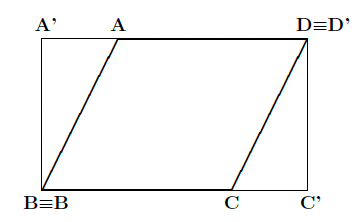
Now, if the three points A, B and C that you have defined are not "orthogonal", i.e. the angle \( \widehat{ABC} \neq 90^\circ\) this would produce an oblique map. To make it rectangular, you can insert the RECTANGU keyword, as shown below:
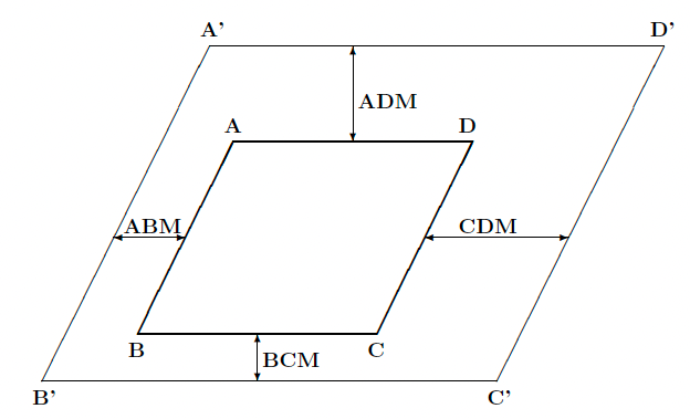
You can also change the explored range in the selected plane (relative to that identified by the three original points A, B and C) by use of the keyword MARGINS, as shown below:
Input examples can be found at this tutorial page.
Hope this helps,
-
-
Thankyou so much. This will help me