Skip to content
  • Home
  • Recent
Collapse
Brand Logo
CRYSTAL23
Latest v1.0.1
Tutorials Try the Demo Get a License
Tutorials Try the Demo Get a License Instagram
aerbaundefined

Alessandro Erba

@aerba
Developer
About
Posts
87
Topics
1
Groups
1
Followers
9
Following
8

Posts

Recent Best Controversial

  • Phonon density of states plotting
    aerbaundefined aerba

    Hi,

    Let me try to rationalize what you observe as follows: In CRYSTAL, interatomic force constants for phonon dispersion are computed with a direct space approach within a supercell. Because of the reciprocity relation between direct and reciprocal lattices, the number of k-points for which phonons can be computed is determined by the expansion factor of the supercell relative to the primitive cell. For instance, with your 2x2 supercell expansion for a 2D system, you get to compute phonons at just 4 k-points. In order to get the phonons at more k-points you can do one of two things (or both):

    1. Increase the supercell expansion (i.e. increase the size of the supercell). Going to 3x3 gives you phonons at 9 k-points, 4x4 gives you phonons at 16 k-points, and so on. This is done through the SCELPHONO keyword:
    SCELPHONO
    6 0
    0 6
    
    1. Interpolate the interatomic force constants to evaluate the dynamical matrices at additional k-points with respect to those determined by the expansion matrix of the supercell. This can be done through the INTERPHESS option as follows:
    INTERPHESS
    8 8
    0
    

    NOTE 1: This interpolation is safe only if the interatomic force constants vanish within the supercell. This usually requires the supercell to have a radius of at least 10-15 Angstroms (i.e. the supercell has to be large).

    NOTE 2: This interpolation is used when phonon bands are computed with BANDS. Thus, the starting supercell has to be large to compute phonon bands safely.

    In your case, what you observe is the following: when you do the BANDS calculation you are doing the interpolation. When you do the PDOS calculation you are not. To add the interpolation in your PDOS calculation (and get a phonon density-of-states that matches that of the phonon band plot) you need to add the INTERPHESS option.

    But, and this is an important but, in this way you would get matching results but they are likely to be both wrong because the supercell you are starting from is too small. To get more reliable results, you need to significantly increase the supercell expansion matrix.

    Hope this helps,


  • Charge State Calculation for periodic System in CRYSTAL17
    aerbaundefined aerba

    Hi,

    To run a calculation with a not neutral unit cell, you must insert the keyword CHARGED at the end of the basis set input block, as in:

    Title
    [geometry]
    END
    [basis set]
    CHARGED
    END
    [SCF parameters]
    END
    

    Hope this helps,


  • MSSC2025 Summer School, 8-12 September 2025, Torino (Italy) "Ab initio Modelling in Solid State Chemistry"
    aerbaundefined aerba

    Dear CRYSTALlers,

    The Theoretical Chemistry Group of the University of Torino and the Department of Chemistry and the Thomas Young Centre at Imperial College London are organising the

    MSSC2025 Summer School on Ab initio Modelling in Solid State Chemistry

    logo_Full.png

    to be held in Torino (Italy), 8-12 September 2025. The School is designed for Master and Ph.D. students, as well as for post-docs and researchers who have an interest in getting or strengthening a background in Computational Solid State Chemistry, Physics, Materials Science, Surface- and Nano-Science.

    The week-long School consists of morning lectures and afternoon hands-on tutorial sessions, where the formal framework and functionalities of the CRYSTAL electronic structure package will be explored.

    Registration opens on March 15 2025. See the School website for further details.

    The School takes place in the elegant city of Torino (Italy):

    Torino.png

    ­
    While we strongly encourage in-person participation, we also offer the possibility to attend remotely through streaming of morning lectures and afternoon hands-on tutorials.

    Participants will have the opportunity to present their research at a poster session.

    See you in Torino!


  • Frequency calculation of very large systems
    aerbaundefined aerba

    Hi,

    I think that the best way to proceed in this case would be to restart the calculation one or more times. To do this, you just have to make sure that the scratch folder is not deleted when the calculation stops. Basically, you would run a first job with:

    FREQCALC
    END
    

    Then, after the first calculation stops (maybe because you reached a wall clock time limit) you would run a second job restarting from the first as:

    FREQCALC
    RESTART
    END
    

    In order to make this restart work, you need a few files from the previous job to be placed in the scratch folder of the new job: FREQINFO.DAT, fort.13 and fort.9 (to be renamed fort.20 in the new folder).

    If needed, you can repeat this restart process multiple times until completion of the frequency calculation.

    Hope this helps,


  • Error in RESTART of FREQCALC calculation
    aerbaundefined aerba

    Hi,

    I am quite familiar with that error message myself: it pops up when the fort.9 unit provided upon the restart is the wrong one (i.e. does not match with the current calculation).

    Let me make a general comment on how to best approach these frequency+intensity calculations with CRYSTAL based on my experience.

    I noticed that you tend to use the PREOPTGEOM option within FREQCALC, and to compute infrared and Raman intensities, all in one shot. Now, this is a very nice feature of CRYSTAL that allows you to run a single job where everything is fully automated: the structure gets optimized, the numerical Hessian computed and diagonalized, and Born and Raman tensors computed. Not many programs can do that, to the best of my knowledge. At the same time, while this is very convenient if you can indeed run everything in a single job, it complicates things if you then need to do a restart from a previous incomplete calculation.

    If you envisage that this could be the case (maybe because of a wall clock limit on the cluster) then it is preferable (to put it mildly) to do things step by step:

    • You first run a geometry optimization with something like:
    [initial geometry]
    
    OPTGEOM
    END
    
    • You prepare a new input file where you insert the optimized geometry from the previous run as a starting point, and perform a frequency calculation, with something like:
    [optimized geometry]
    
    FREQCALC
    END
    
    • If this calculation stops, you can now restart it easily with:
    [optimized geometry]
    
    FREQCALC
    RESTART
    END
    

    by providing the required restart files (FREQINFO.DAT and fort.13 from the first frequency calculation, and fort.9 from the geometry optimization, to be renamed fort.20 in the new scratch folder).

    • Once the restart is done and the frequency calculation is complete, you can compute the intensities, with something like:
    [optimized geometry]
    
    FREQCALC
    RESTART
    INTENS
    INTRAMAN
    INTCPHF
    ENDCPHF
    END
    

    Personally, I always do things separately, running first the geometry optimization, then the Hessian (i.e. harmonic frequency) calculation, then the intensities through CPHF/KS in three separate jobs.

    Hope this clarifies things a little,


  • Is there a software to create DOS/BAND input?
    aerbaundefined aerba

    Hi,

    I haven't used it in a while but I remember XCrySDen had a GUI for k path selection.

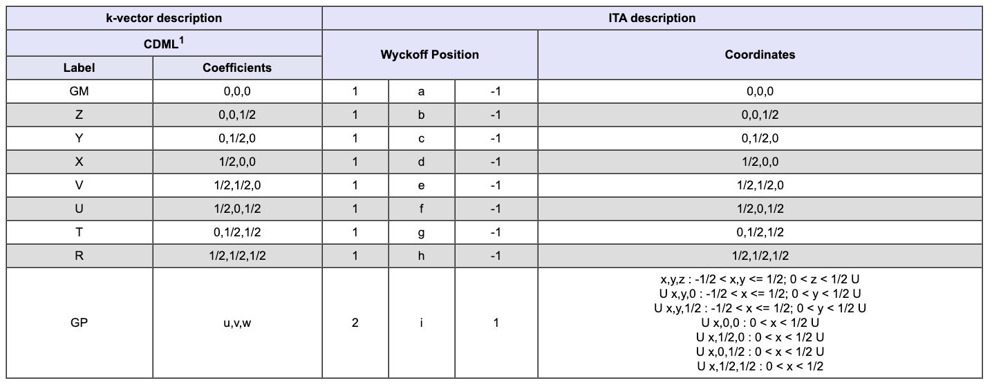
    What I typically do instead is use the Bilbao Crystallographic Server as a guide. If you navigate to "Space-group Symmetry" and then to "KVEC: The k-vector types and Brillouin zones of Space Groups", you will be able to select your space group of interest and then click on "Comparative listing of k-vector types".

    For instance, for your P-1 space group you get:

    Screenshot 2025-07-23 alle 08.42.42.png

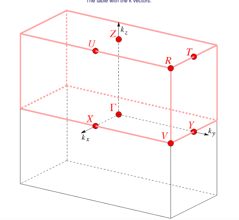
    where you can find the coordinates of the high symmetry special points listed in the table (NOTE: if your space group admits a crystallographic cell that differs from the primitive cell, you will find both sets of coordinates in the table. Make sure you use the primitive ones to write the BAND input in the .d3 file) and also inspect the Brillouin zone:

    Screenshot 2025-07-23 alle 08.43.02.png

    The order at which you explore these points does not really matter (unless you want to reproduce a specific path from some reference plot), as long as you explore most/all of them.

    Hope this helps,


  • IR and Raman frequency calculations at different temperature
    aerbaundefined aerba

    Hi,

    By default, thermodynamic properties on top of harmonic frequencies are computed at room temperature. Different values of temperature can be explored by use of the TEMPERAT keyword. To restart the harmonic frequency calculation, use the RESTART keyword. An example is given below:

    FREQCALC
    RESTART
    TEMPERAT
    5 200 600
    END
    

    With the input above, thermodynamic properties will be computed and printed at 5 temperatures, equally spaced in the range 200-600 K.


  • Confusion in PIEZOCON
    aerbaundefined aerba

    Hi,

    Direct piezoelectric constants of a 3D lattice in CRYSTAL are defined and computed as:
    $$
    e_{ci}^{3D} = \left( \frac{\partial P_c}{\partial \eta_i}\right) = \frac{1}{V}\left( \frac{\partial^2 E}{\partial E_c\partial \eta_i}\right)
    $$
    that is as first derivatives of Cartesian components of the polarization (c=x,y,z) with respect to strain components, or, equivalently as second derivatives of the energy density (V is the volume of the 3D lattice cell) with respect to Cartesian components of an electric field \(E_c\) and strain components, where the strain \( \eta \) is dimensionless and thus the direct piezoelectric constants have units of \( \textup{charge/length}^2 \).

    For 1D and 2D periodic lattices, as the volume (V) is not uniquely defined (or not defined at all in some cases), one may divide by the length \(l \) and area \( A\) of the lattice cell instead:
    $$
    e_{ci}^{1D} = \frac{1}{l}\left( \frac{\partial^2 E}{\partial E_c\partial \eta_i}\right) \quad \textup{and} \quad e_{ci}^{2D} = \frac{1}{A}\left( \frac{\partial^2 E}{\partial E_c\partial \eta_i}\right)
    $$
    that would thus be expressed in units of \( \textup{charge} \) or \( \textup{charge/length} \) for 1D and 2D lattices, respectively.

    However, in CRYSTAL for 1D and 2D lattices we do not divide by \(l \) or \( A\) , and just define and compute the piezoelectric constants as:
    $$
    e_{ci}^\textup{1D and 2D} = \left( \frac{\partial^2 E}{\partial E_c\partial \eta_i}\right)
    $$
    with units of \( \textup{charge}\cdot\textup{length} \).

    Yes, these constants are physically meaningful for 1D and 2D systems. For a 2D monolayer system, for instance, depending on what you need to compare with, you can do one of two things:

    • keep them as they are printed in the CRYSTAL output (units of \( \textup{charge}\cdot\textup{length} \))

    • divide the values you get in the CRYSTAL output by the area of the 2D cell (and thus express them in units of \( \textup{charge/length} \))

    I would not divide by a volume because I would not know the physical meaning of the volume of a 2D monolayer system.

    Hope this helps,


  • Error in RESTART of FREQCALC calculation
    aerbaundefined aerba

    Hi,

    I have run some calculations on your case following my step-by step recipe (as described at https://forum.crystalsolutions.eu/post/339, which I have now edited to include the intensity step), and the restart now works just fine (i.e. without the annoying "possibly conducting state", and with a nice convergence of the further SCFs upon restart).

    This is what I did:

    • I took the optimized geometry from your original output file and I created a new input file for a single-point calculation. I ran it and obtained the wavefunction external file (i.e. fort.9 unit);

    • I prepared an input file to run the harmonic frequency calculation, I ran it and I killed it in the middle of the construction of the Hessian. From this incomplete frequency calculation, I obtained the FREQINFO.DAT file and the external unit with the density matrix, i.e. fort.13 unit;

    • I prepared an input file to restart the frequency calculation and provided the FREQINFO.DAT and fort.13 files from the previous step and the fort.9 (renamed as fort.20) from the first step, and ran it. The calculation of the Hessian restarted correctly, with the new SCFs converging nicely (see the attached SCFOUT.LOG file). I then stopped the calculation not to use too much compute power on my cluster.

    If you follow this step-by-step process you'll be able to safely restart your frequency calculations.

    Hope this helps,


  • computing anharmonic shifts for C-H vibrations
    aerbaundefined aerba

    Hi,

    In CRYSTAL23, the anharmonicity of a given vibration mode - or of a set thereof - can be computed via: I) the evaluation of cubic and quartic interatomic force constants (in the basis of the normal modes) followed by II) the solution of the nuclear Schroedinger equation with either the vibrational self-consistent field (VSCF) or vibrational configuration interaction (VCI) method.

    Details on the actual implementation of steps I) and II) can be found here:

    I) Anharmonic force constants

    II) VSCF and VCI for solids

    Step-by-step, the procedure is as follows:

    1. Geometry optimization to fully relax atomic positions within the cell (OPTGEOM keyword);
    2. Harmonic frequency calculation (FREQCALC keyword);
    3. Selection of the normal modes for which the anharmonic correction is to be computed (for instance, in your case, those corresponding to C-H stretching vibrations);
    4. Calculation of cubic and quartic interatomic force constants for the selected modes + VSCF (or VCI) calculation of anharmonic states.

    As an example, let' s assume that C-H stretching vibrations correspond to modes 15-20 in the list generated from the harmonic calculation (that is, there are 6 different C-H stretching modes). The input for steps 3. and 4. above would read:

    FREQCALC
    RESTART
    ANHAPES
    6
    15 16 17 18 19 20
    3 0.9
    VSCF
    END
    

    that is, we restart the harmonic frequency calculation, and where 6 is the number of modes, 15 16 17 18 19 20 are the selected modes, and 3 0.9 are two parameters specifying the numerical approach used for the evaluation of cubic and quartic force constants.

    Please, note that with such a calculation not only the "intrinsic" anharmonicity of each selected mode is evaluated but also the couplings among all selected modes. If, instead, one just wants to compute the "intrinsic" anharmonicity with no couplings, independent calculations can be run, one per each selected mode.

    Visit this page for a tutorial on anharmonic calculations in CRYSTAL


  • Error reading end of file when visualizing Raman vibrational modes
    aerbaundefined aerba

    Hi,

    We've been running some tests. This is what we found: Vibration Mode Animations on CRYSPLOT are run through JSmol, which does not seem to correctly read a CRYSTAL output file if the option FRAGMENT is used. Without FRAGMENT everything works fine.

    We could read your FRAGMENT output file and correctly visualize animations of the modes by using the MOLDRAW package instead.


  • Confusion in ELASTCON output:
    aerbaundefined aerba

    Hi,

    Elastic constants of a 3D lattice in CRYSTAL are defined and computed as:

    $$
    C_{ij}^\textup{3D} = \frac{1}{V} \left( \frac{\partial^2 E}{\partial \eta_i \partial \eta_j}\right)
    $$

    where the strain \( \eta \) is dimensionless and thus the elastic constants have units of \( \textup{energy/length}^3 \), which corresponds to force/surface (i.e. a pressure).

    For 1D and 2D periodic lattices, as the volume \(V\) is not defined, one may divide by the length \(l \) and area \( A\) of the lattice cell instead:

    $$
    C_{ij}^\textup{1D} = \frac{1}{l} \left( \frac{\partial^2 E}{\partial \eta_i \partial \eta_j}\right) \qquad \textup{and} \qquad C_{ij}^\textup{2D} = \frac{1}{A} \left( \frac{\partial^2 E}{\partial \eta_i \partial \eta_j}\right)
    $$

    However, in CRYSTAL for 1D and 2D lattices we do not divide by \(l \) or \( A\) , and just define and compute the elastic constants as:

    $$
    C_{ij}^\textup{1D and 2D} = \left( \frac{\partial^2 E}{\partial \eta_i \partial \eta_j}\right)
    $$

    with units of energy. So, starting from the constants printed in the CRYSTAL output all you have to do is divide by the area of the 2D cell if you need them expressed in \( \textup{energy/length}^2 \).


  • Imaginary frequencies
    aerbaundefined aerba

    Hi,

    The presence of imaginary frequencies is a sign that the geometry is not a minimum of the potential energy surface (PES). In general, this may due to two main factors:

    1) A somewhat loose overall numerical precision in the geometry optimization + harmonic frequencies calculation. Here, it seems that you have already explored a few parameters. We can distinguish between parameters governing the overall numerical precision of the SCF + forces calculations, and those that are specific to the evaluation of the Hessian:

    1.1) Precision of SCF+forces

    One may increase a bit the thresholds for the screening of two-electron integrals (TOLINTEG keyword), switch-off the bipolar approximation (NOBIPOLA keyword), increase the shrinking factor (SHRINK keyword), use a denser grid for numerical integration of the exchange-correlation term (see XLGRID, XXLGRID keywords), tighten the convergence criteria for the SCF (setting TOLDEE to 10 or 11 for instance), tighten the convergence criteria for the geometry optimization step (see TOLDEG and TOLDEX keywords).

    1.2) Numerical evaluation of the Hessian

    In many cases, a more numerically stable evaluation of the Hessian is achieved by use of a two-sided finite difference approach (rather than the default one-sided approach). This can be activated with the NUMDERIV keyword within the FREQCALC input block as follows:

    FREQCALC
    NUMDERIV
    2
    ENDFREQ
    

    2) The presence of symmetry-constraints that prevent the optimizer to get to the minimum of the PES. If this is the case, removing symmetry constraints may be key to reach the minimum. This can be done by use of the SYMMREMO keyword (to be inserted in the geometry input block).


  • MP2 single points
    aerbaundefined aerba

    Hi,

    The MP2 option is no longer supported in recent versions of the CRYSTAl program. If you are interested in a periodic MP2 calculation, my suggestion is to contact Lorenzo Maschio ([email protected]) and Denis Usvyat ([email protected]) directly, who may provide guidance in the use of the CRYSCOR program.


  • Error reading end of file when visualizing Raman vibrational modes
    aerbaundefined aerba

    Hi,

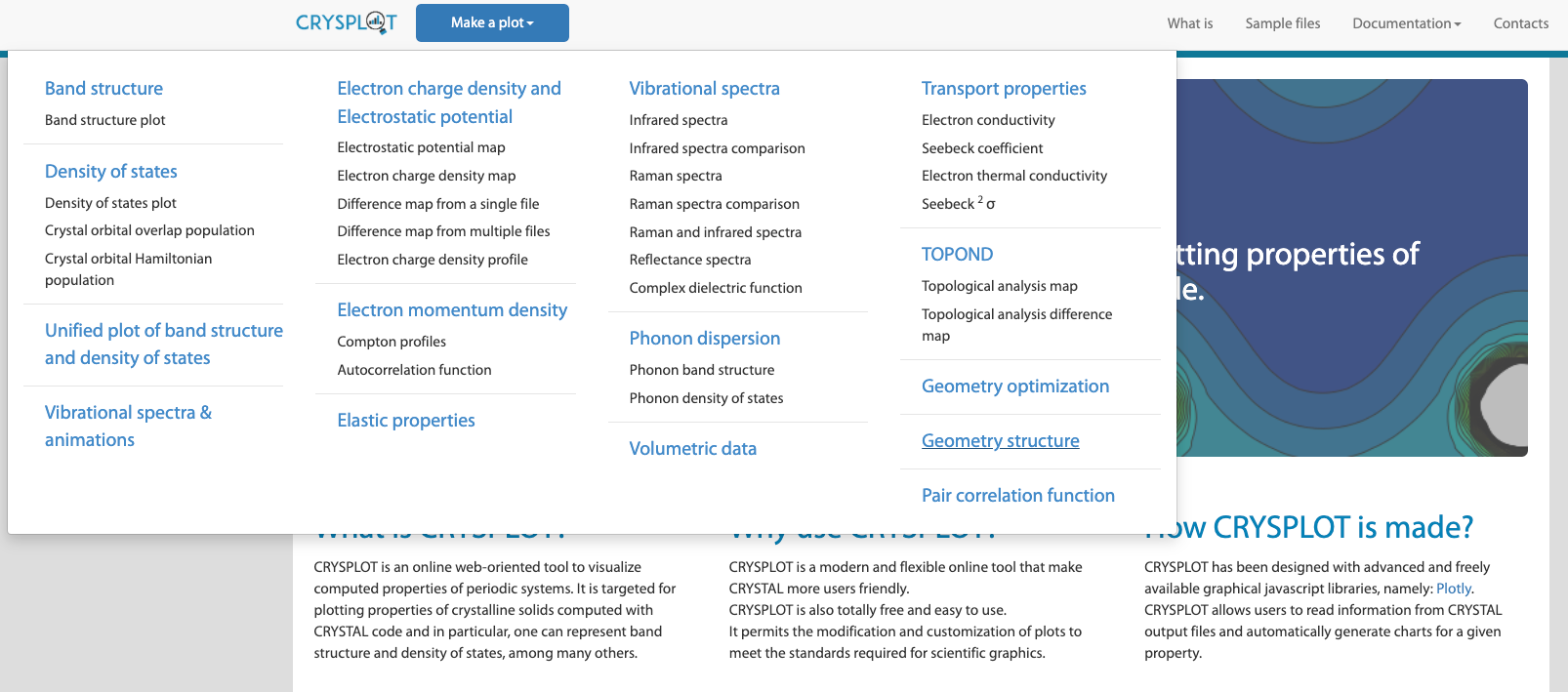
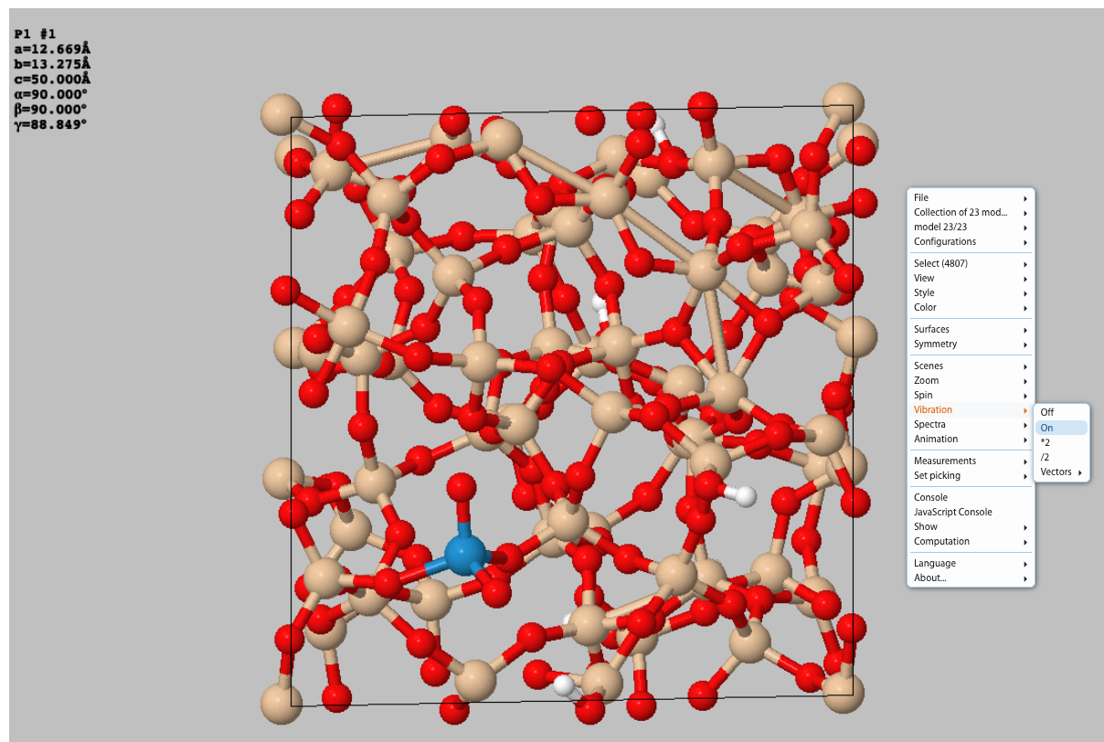
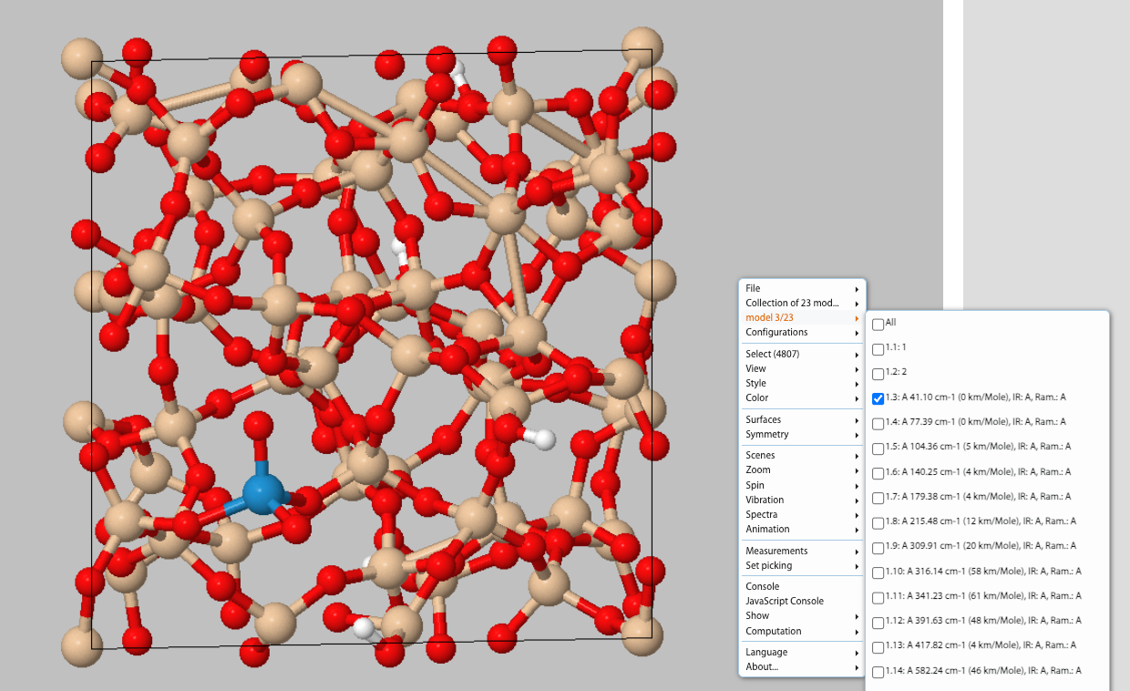
    We have found a workaround that allows you to visualize animations of normal modes from CRYSPLOT also from a FRAGMENT calculation.

    1. Go to CRYSPLOT and from the "Make a Plot" menu select "Geometry Structure" (bottom-right)

    Screenshot 2025-04-01 alle 14.41.45.png

    1. Select and upload your output file (.out)

    2. By right-clicking with your mouse select "Vibration" and set it to "On":

    Screenshot 2025-04-01 alle 14.42.37.png

    1. At this point, by right-clicking with your mouse select "Model x/23" and select desired Mode from list to animate it:

    Screenshot 2025-04-01 alle 14.43.06.png

    Hope this helps


  • fort.62 issue
    aerbaundefined aerba

    Hi,

    Just a couple of comments:

    1. Are you starting from a fully optimized structure? I ask because the following warning is printed in your output file:
    WARNING!! FORCE   9 AT CENTRAL POINT IS GREATER THAN 10^-4. OPTIMIZE THE STRUCTURE AND RE-RUN
    
    1. Anisotropic shrinking factors are not fully supported by ELAPIEZO calculations, which may be at the origin of the problem you are experiencing. I would advise to try running the calculation with an isotropic shrinking factor. Something like:
    SHRINK
    3 3
    

    Let us know if this helps,


  • Question about basic principle of pressure and frequency calculation
    aerbaundefined aerba

    Hi,

    I understand your confusion, which originates from the fact that PRESSURE is an old option of FREQCALC that indeed does not apply any pressure. With this option, the structure is unchanged, the forces are unchanged, and ultimately, the harmonic vibration frequencies are unchanged. The only bit of information that is affected by this keyword is the printed value of the PV term in the thermodynamic analysis.

    So, this PRESSURE keyword within FREQCALC should be used in just one way: to set the value of pressure corresponding to the structure used to run the harmonic frequency calculation, so as to have the PV term entering the thermodynamic functions (enthalpy and Gibbs free energy) right. Let me make a couple of examples:

    1. You perform a full structural relaxation (atomic positions + lattice parameters). Thus, you have a zero pressure (p=0) structure. Then you compute the harmonic frequencies. If you are interested in thermodynamic potentials (i.e. enthalpy, Gibbs, Helmholtz, etc.) you should use the PRESSURE keyword and set the pressure to zero to get the PV term right in the output (otherwise by default it would be computed at p = 1 atm - do not ask me why).

    2. You perform a pressure-constrained geometry optimization with the EXTPRESS keyword of OPTGEOM (let's say at 29.457 GPa as in your example). Then you compute harmonic frequencies with FREQCALC on this compressed structure. Now, again, if you are interested in thermodynamic potentials (i.e. enthalpy, Gibbs, Helmholtz, etc.) you should use the PRESSURE keyword and set the pressure to 29.457 GPa to get the PV term right in the output.

    So, as I said at the beginning, the PRESSURE keyword here does not change anything on the structure/forces. It only allows you to tell the program what is the pressure of the structure you are working on, so that the printed PV term is right.

    A more formally-sound way to combine temperature and pressure is provided by the quasi-harmonic approximation: See Eq. (13) of the tutorial page on the Quasi-Harmonic Approximation (QHA).

    Hope this helps clarifying things a little,


  • Error with external electric field
    aerbaundefined aerba

    Hi,

    The two options you are using, FIELDCON and FIELD, apply a finite electric field along non-periodic and periodic directions, respectively. Thus, FIELDCON can be used for low-dimensional systems (1D, 2D) only.

    When the finite electric field is applied along a periodic direction (FIELD option), a supercell must be built along that direction, which requires additional input parameters with respect to the FIELDCON option. A complete input in your case would look something like:

    FIELD
    0.00194467
    0 0 1
    4 1
    40 1
    

    where 4 is the supercell expansion factor along the periodic direction of the field and 40 is the number of Fourier terms for the triangular potential expansion.

    For a detailed description of the use of FIELD and FIELDCON, please refer to this tutorial page.

    Note

    Please, be aware that a more analytical approach is available in CRYSTAL to compute the optical dielectric tensor of a system - that does not require any supercell to be built - through the coupled-perturbed Kohn-Sham (CPKS) method. The input for this option is simply:

    CPKS
    END
    

    to be inserted before the END of the geometry input block.

    You can find a tutorial page on CPKS here.

    We do strongly encourage to use CPKS rather than FIELD unless strictly needed.


  • Usage of the RESTART Keyword
    aerbaundefined aerba

    Hi,

    Hessian information is indeed contained in the OPTINFO.DAT file, as is information on the last geometry of the previous run so that it is indeed unnecessary to manually update the geometry in the new input.

    This is not so clear from the documentation: I had to check in the code 🙂

    Hope this clarifies things a little


  • SCANMODE io error Read_int_1d
    aerbaundefined aerba

    Hi,

    job314 said in SCANMODE io error Read_int_1d:

    So it turns out having fort.13 and fort.20 is not optional for restart.

    Yes, the lack of these two files was the origin of the I/O error.

    job314 said in SCANMODE io error Read_int_1d:

    PS. I would also like to ask developers to allow uploading compressed files to this forum

    Now also .zip, .tar, .tgz, .tar.gz files can be uploaded.

    Cheers,

  • Login

  • Don't have an account? Register

  • Login or register to search.
  • First post
    Last post
0
  • Home
  • Recent