Of course, in no case an isolated molecule would have access to neighboring functions. But in the crystal it does. If its own basis is not complete, a molecule in the crystal can get extra-stabilized by the neighboring functions not because of a "physical" or "chemical" interaction with neighboring molecules but because of an artifact due to the incompleteness of its basis. So if you were to compute the cohesive energy just as energy of the crystal - energy of the bare molecule, you would get an extra unphysical interaction. To make sure you get the right cohesive energy you could do one of two things: i) remove the extra interaction from the calculation on the crystal; ii) add it also to the molecular calculation so that it cancels when taking the difference (this is the MOLEBSSE strategy, also known as Boys-Bernardi counterpoise correction).
Alessandro Erba
Posts
-
MOLEBSSE -
MOLEBSSEHi Jonas,
As you correctly point out, in this case the molecular calculations are not affected by BSSE as you are extracting a single molecule (i.e. with no neighbors).
The calculation that is affected by BSSE is the one on the crystal, where each molecule within the molecular crystal could potentially "benefit" from the basis functions of the neighboring molecules if its own basis is not complete. So we use MOLEBSSE for this, to make sure we compare apples with apples (i.e. the energy of a molecule in the crystal that has access to the basis functions from neighboring molecules, with the energy of an isolated molecule that also has access to the same neighboring basis functions).
Hope this helps clarifying things a little,
-
Query regarding the 'PS' label of TOPOND output -
BETAVIB (Vibrational contribution to the SHG and Electro Optic-Effect) -
BETAVIB (Vibrational contribution to the SHG and Electro Optic-Effect)Hi,
We have checked the implementation. The values printed in the output of the BETAVIB calculation for SHG and Pockels are expressed in atomic units and correspond to \( \frac{1}{2}{\boldsymbol{ \beta}} \). That is, the factor of \( \frac{2\pi}{V} \) seems to be missing to make them the d tensor. In other words, by multiplying the values in the output by \( \frac{2\pi}{V} \) you should get d.
Please, let me know if you think this makes sense based on the values you get for your system.
Sorry for the confusion.
Hope this helps, -
Stability calculationsFormally, if finite temperature effects are to be included, the internal static energy E needs to be substituted with the free energy F in the definition of the Hessian. This is easier said than done. However, for the elastic tensor, we do have an implementation to compute free energy derivatives with respect to lattice strain (i.e. thermo-elasticity). See also:
https://www.mdpi.com/2075-163X/9/1/16
The elastic tensor is not defined for 0D systems, where you could just explore the "dynamical stability" in terms of the vibration frequencies.
-
Stability calculationsHi,
Stability is a broad concept that can be interpreted and analyzed in many ways. One way to look at it is the following: checking whether or not the Hessian of second energy derivatives is positive-definite (all eigenvalues are positive) or not, i.e. if the structure is a local minimum of the potential energy surface (PES). Indeed if small structural perturbations produce an energy decrease rather than increase (that is if some of the eigenvalues are negative) the structure can not be considered "stable".
Two types of Hessian matrix can be considered, which correspond to two types of stability:
-
Hessian with respect to atomic displacements within a fixed cell for dynamical (phonon) stability. This corresponds to checking if all harmonic frequencies are positive.
-
Hessian with respect to lattice distortions for mechanical stability (so-called Born stability conditions). This corresponds to checking if all the eigenvalues of the elastic tensor are positive.
Hope this helps,
-
-
BETAVIB (Vibrational contribution to the SHG and Electro Optic-Effect) -
phonon dispersion in thermoHi Jonas,
When computing thermodynamic properties, we should set up a canonical partition function over all vibrational states of the lattice, which includes phonons at all k points within the first Brillouin zone in principle. The partition function, and thus thermodynamic properties, tend to converge as the sampling of phonons at different k points improves.
As an example, consider what happens for the specific heat and vibrational entropy of MgO in the picture below, where lines of increasing thickness correspond to calculations on larger supercells (i.e. to richer k sampling):
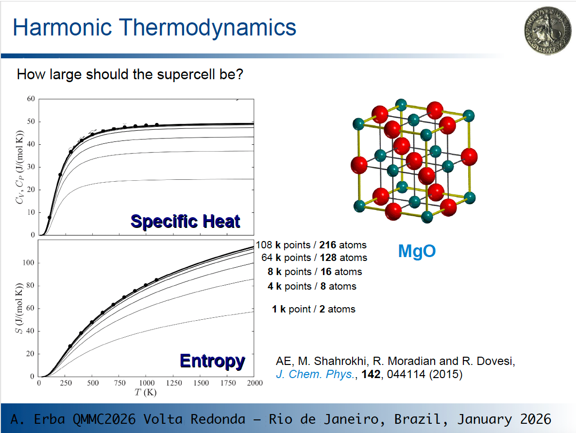
As you see, thermodynamic values change and eventually converge!
So, depending on the size of the original cell, phonon dispersion can have a very large effect on computed thermodynamic properties. This is particularly evident for MgO where the original cell is very small.
So, going back to one of your questions: "how large should the supercell be?" You should use the smallest cell that allows you to get converged results. How to determine it? By progressively increasing the size and by checking your results.
The rule of thumb you suggest of using supercells for different systems containing a similar number of atoms is a good guideline for consistent expansions across different systems.
Hope this helps,
-
Plotting band-decomposed charge density (CBM/VBM) for 2D Janus monolayerHi,
To analyze conduction bands I can recommend a couple of options:
-
Decomposition of selected bands into leading AO contributions. This option allows to characterize the nature of a band at a given k point in terms of the main AOs contributing to it. From the PROPERTIES module, refer to the ANBD keyword, see page 307 of the User's Manual.
-
3D plotting of crystalline orbitals. From the PROPERTIES module, refer to the ORBITALS keyword, see page 347 of the User's Manual.
Hope this helps,
-
-
Raman tensor outputHi,
Indeed, columns of the TENS_RAMAN.DAT file correspond to xx, ..., zz components of the polarizability tensor \( \alpha \). However, rows correspond to the 3N atomic Cartesian displacements. Indeed, the Raman tensor reported in this file corresponds to the following quantity:
$$
R_{ac,ij} = \frac{\partial^3 E}{\partial u_{a,c} \partial \varepsilon_i \partial \varepsilon_j} = \frac{\partial \alpha_{ij}}{\partial u_{a,c} }
$$
where \( \varepsilon_i \) is a Cartesian component of the electric field, and \( u_{a,c} \) is an atomic displacement of atom \( a \) along the \( c\)-th Cartesian direction. The values are reported in atomic units.Hope this helps,
-
Options to print KS potentialHi,
With CRYSTAL (from the PROPERTIES module actually) one can output the Hartree+EN potential in the all-electron case in 2D or 3D grids with POTM and POT3 keywords, respectively. In the latter case, the output is in .cube format. But I am afraid that currently there is no keyword to plot the XC part of the potential on a grid.
-
Plotting band-decomposed charge density (CBM/VBM) for 2D Janus monolayerHi,
You can do this using the PROPERTIES module. The PBAN option [see CRYSTAL23 User's Manual at page 348] allows you to build a density matrix from a user-defined subset of electronic bands. This partial density matrix is used for subsequent calculations. The ECH3 option can then be used to evaluate the associated electron density on a user-defined 3D grid of points, to be stored in .cube format, which can then be plotted in 3D isosurfaces with standard visualizers, such as VESTA.
A template .d3 PROPERTIES input file for this would look something like:
NOSYMADA
NEWK
24 24
1 0
PBAN
1
14
ECH3
80
RANGE
-10 10
END
where in PBAN as an example I have selected just 1 band, number 14 in the list.
Hope this helps,
-
Advanced School on Quantum Modelling of Materials with CRYSTAL - Volta Redonda -
Question about units of "total atomic spins" -
malloc during BOLTZTRA (Pproperties)Hi,
We have run some tests and we have identified the origin of the problem. The calculation fails in the evaluation of the Fermi energy in the NEWK option (so before getting to the BOLTZTRA step) because of large memory requirements due to a very large number of k-points being asked and because of the replicated-memory parallel implementation of that bit of code.
In that part of the code, with Pproperties (parallel version), data are replicated in memory by each process.
We have run tests on this system in parallel with different number of processes (on a computing node with 128 CPU cores) and for different shrinking factor parameters of the NEWK keyword. Results are summarized in the table below:
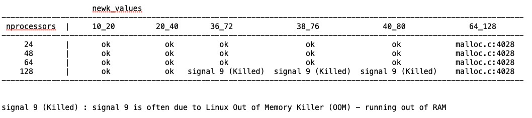
"ok" marks combinations for which the calculation run without errors. The trend is clear and can be rationalized as follows:
- reducing the number of k points reduces memory requirments
- reducing the number of MPI processes effectively increases the available memory/process
Hope this clarifies things and helps find a way forward,
-
How to obtain the irreducible representations of the electronic bands ?Hi,
I used space group 186 for ZnO that corresponds to the one you mention. In the character table printed by CRYSTAL only those irreps that are actually used to build symmetry-adapted Bloch functions are shown. I have updated my original post above to show the irrep labels in the character tables, which match those found in the printing of the eigenvalues.
Hope this clarifies things,
-
How to obtain the irreducible representations of the electronic bands ?Hi,
The following keyword combination to be inserted in the third block of the .d12 CRYSTAL input file works for me on a 3D crystal (I have tried on ZnO as a test):
SETPRINT
2
47 10
66 10
KSYMMPRT
The keyword KSYMMPRT activates a printing level with character tables for the various k little groups. With SETPRINT you set other printing options: option 47 refers to KSYMMPRT while option 66 activates the printing of the eigenvalues. With 10 in both cases I am asking for detailed printing for the first 10 k points in the list. Just increase this parameter from 10 to X for detailed information on the first X k points.
At the end of the SCF, in the output file you will find detailed symmetry information. For ZnO, for instance:
+++ SYMMETRY ADAPTION OF THE BLOCH FUNCTIONS +++

 SYMMETRY INFORMATION:
 K-LITTLE GROUP: CLASS TABLE, CHARACTER TABLE.
 IRREP-(DIMENSION, NO. IRREDUCIBLE SETS)
 (P, D, RP, RD, STAND FOR PAIRING, DOUBLING, REAL PAIRING AND REAL DOUBLING
 OF THE IRREPS (SEE MANUAL))

 CLASS  | GROUP OPERATORS (SEE SYMMOPS KEYWORD)
 --------------------------------------------------------------------
 C2     |   2;
 C3     |   3;   4;
 C6     |   5;   6;
 SGV    |   7;   8;   9;
 SGV'   |  10;  12;  11;

 IRREP/CLA      E     C2     C3     C6    SGV   SGV'
 ---------------------------------------------------
  MULTIP |      1      1      2      2      3      3
 ---------------------------------------------------
    A    |   1.00   1.00   1.00   1.00   1.00   1.00
    B    |   1.00  -1.00   1.00  -1.00   1.00  -1.00
    E1   |   2.00  -2.00  -1.00   1.00   0.00   0.00
    E2   |   2.00   2.00  -1.00  -1.00   0.00   0.00

 A  -(1,  21); B  -(1,  21); E1 -(2,  15); E2 -(2,  15);


 CLASS  | GROUP OPERATORS (SEE SYMMOPS KEYWORD)
 --------------------------------------------------------------------
 C2     |   8;

 IRREP/CLA      E     C2
 -----------------------
  MULTIP |      1      1
 -----------------------
    A    |   1.00   1.00
    B    |   1.00  -1.00

 A  -(1,  72); B  -(1,  30);


[...]
And information about the eigenvalues at each k point with the associated irrep symmetry label:
 FINAL EIGENVALUES (A.U.)
  (LABELS REFER TO SYMMETRY CLASSIFICATION)

   1 (  0  0  0)
 -3.4563E+02(B  ) -3.4563E+02(A  ) -4.1575E+01(B  ) -4.1575E+01(A  ) -3.6643E+01(A  )
 -3.6643E+01(B  ) -3.6643E+01(E1 ) -3.6643E+01(E1 ) -3.6642E+01(E2 ) -3.6642E+01(E2 )
 -1.8704E+01(A  ) -1.8704E+01(B  ) -4.5481E+00(A  ) -4.5481E+00(B  ) -2.9815E+00(B  )
 -2.9814E+00(A  ) -2.9812E+00(E2 ) -2.9812E+00(E2 ) -2.9812E+00(E1 ) -2.9812E+00(E1 )
 -8.2115E-01(A  ) -7.9663E-01(B  ) -3.8298E-01(E1 ) -3.8298E-01(E1 ) -3.8023E-01(A  )
 -3.7674E-01(E2 ) -3.7674E-01(E2 ) -3.6589E-01(B  ) -3.4625E-01(E1 ) -3.4625E-01(E1 )
 -3.3970E-01(E2 ) -3.3970E-01(E2 ) -3.2752E-01(B  ) -2.0184E-01(E2 ) -2.0184E-01(E2 )
 -1.7704E-01(A  ) -1.7506E-01(E1 ) -1.7506E-01(E1 ) -1.3296E-01(A  )  2.8917E-02(B  )
  1.3748E-01(B  )  3.0394E-01(E1 )  3.0394E-01(E1 )  3.4544E-01(E2 )  3.4544E-01(E2 )
  3.5105E-01(A  )  7.3399E-01(A  )  7.9567E-01(B  )  7.9827E-01(E2 )  7.9827E-01(E2 )
  8.0430E-01(E1 )  8.0430E-01(E1 )  9.2452E-01(E1 )  9.2452E-01(E1 )  9.4481E-01(A  )
  1.0085E+00(E2 )  1.0085E+00(E2 )  1.0835E+00(B  )  1.1254E+00(A  )  1.4388E+00(E2 )
  1.4388E+00(E2 )  1.5197E+00(E1 )  1.5197E+00(E1 )  1.5953E+00(B  )  1.6980E+00(A  )
  1.9424E+00(B  )  2.1214E+00(B  )  2.4581E+00(E2 )  2.4581E+00(E2 )  2.6850E+00(A  )
  2.6884E+00(E1 )  2.6884E+00(E1 )  2.6992E+00(B  )  2.7357E+00(E1 )  2.7357E+00(E1 )
  2.7753E+00(E2 )  2.7753E+00(E2 )  3.0348E+00(E2 )  3.0348E+00(E2 )  3.1219E+00(E1 )
  3.1219E+00(E1 )  3.1318E+00(A  )  4.2450E+00(E2 )  4.2450E+00(E2 )  4.2830E+00(A  )
  4.4957E+00(E1 )  4.4957E+00(E1 )  4.5498E+00(E1 )  4.5498E+00(E1 )  4.7190E+00(B  )
  4.7730E+00(E2 )  4.7730E+00(E2 )  4.7949E+00(A  )  4.8374E+00(E2 )  4.8374E+00(E2 )
  4.8743E+00(B  )  5.0462E+00(E1 )  5.0462E+00(E1 )  5.4477E+00(A  )  5.8198E+00(B  )
  3.9355E+01(B  )  3.9424E+01(A  )

   2 (  1  0  0)
 -3.4563E+02(A  ) -3.4563E+02(A  ) -4.1575E+01(A  ) -4.1575E+01(A  ) -3.6643E+01(A  )
 -3.6643E+01(A  ) -3.6643E+01(B  ) -3.6642E+01(A  ) -3.6642E+01(B  ) -3.6642E+01(A  )
 -1.8704E+01(A  ) -1.8704E+01(A  ) -4.5481E+00(A  ) -4.5481E+00(A  ) -2.9815E+00(A  )
 -2.9814E+00(A  ) -2.9812E+00(A  ) -2.9812E+00(B  ) -2.9812E+00(A  ) -2.9812E+00(B  )
 -8.1833E-01(A  ) -7.9542E-01(A  ) -3.8502E-01(A  ) -3.8129E-01(B  ) -3.7873E-01(A  )
 -3.7647E-01(A  ) -3.7434E-01(B  ) -3.6339E-01(A  ) -3.4716E-01(A  ) -3.4630E-01(B  )
 -3.3948E-01(B  ) -3.3567E-01(A  ) -3.2769E-01(A  ) -2.2123E-01(A  ) -2.0904E-01(B  )
 -2.0238E-01(A  ) -1.8061E-01(A  ) -1.7889E-01(B  ) -9.9076E-02(A  )  5.0288E-02(A  )
  1.3868E-01(A  )  2.6653E-01(A  )  3.0802E-01(B  )  3.1234E-01(A  )  3.5046E-01(B  )
  3.5371E-01(A  )  7.3602E-01(A  )  7.7587E-01(B  )  7.9991E-01(A  )  8.0492E-01(A  )
  8.3924E-01(B  )  8.5620E-01(A  )  9.3227E-01(A  )  9.3403E-01(B  )  9.5348E-01(A  )
  9.9448E-01(A  )  1.0316E+00(B  )  1.1292E+00(A  )  1.1707E+00(A  )  1.3826E+00(A  )
  1.4008E+00(B  )  1.5217E+00(B  )  1.5347E+00(A  )  1.6362E+00(A  )  1.7168E+00(A  )
  1.9795E+00(A  )  2.1273E+00(A  )  2.4524E+00(B  )  2.4562E+00(A  )  2.6427E+00(A  )
  2.6752E+00(B  )  2.6832E+00(A  )  2.6862E+00(A  )  2.7057E+00(B  )  2.7063E+00(A  )
  2.7671E+00(B  )  2.7722E+00(A  )  2.9842E+00(A  )  3.0206E+00(B  )  3.0849E+00(A  )
  3.1311E+00(B  )  3.1382E+00(A  )  4.2311E+00(A  )  4.2454E+00(B  )  4.2544E+00(A  )
  4.4759E+00(B  )  4.4850E+00(A  )  4.5531E+00(B  )  4.5945E+00(A  )  4.6563E+00(A  )
  4.7965E+00(A  )  4.8056E+00(B  )  4.8150E+00(B  )  4.8262E+00(A  )  4.9013E+00(A  )
  4.9403E+00(A  )  5.0500E+00(B  )  5.0510E+00(A  )  5.5124E+00(A  )  5.8464E+00(A  )
  3.9366E+01(A  )  3.9416E+01(A  )

[...]
Hope this helps,
-
Frequency calculation fails with "Too much data, unit 2"Hi,
Thank you for reporting this.
While we run some tests on our cluster, may I suggest switching from a coupled-perturbed Kohn-Sham (CPKS) approach to a Berry phase (BP) approach for the IR intensities? The latter is way less computationally demanding than the former and in this case could be beneficial to the success of the calculation.
You are currently using CPKS as per your input file:
FREQCALC
NOECKART
INTENS
INTCPHF
FMIXING
60
ANDERSON
MAXCYCLE
300
ENDCPHF
ENDFREQ
To switch to BP, you can use instead:
FREQCALC
NOECKART
INTENS
ENDFREQ
Let me know how this goes,
-
Question on HSE06 + SOC Support and MPI Abort in CRYSTAL23