Skip to content
  • Home
  • Recent
Collapse
Brand Logo
CRYSTAL23
Latest v1.0.1
Tutorials Try the Demo Get a License
Tutorials Try the Demo Get a License Instagram
aerba

Alessandro Erba

@aerba
Developer
Unfollow Follow
About
Posts
115
Topics
1
Shares
0
Groups
1
Followers
9
Following
8

Posts

Recent Best Controversial

  • P 21/a symmetry not found
    aerba aerba
    Geometry Editing

    Hi,

    I think it was just a syntax problem on the way the symbol of the space group was inputted. This is how it should look like in this case:

    TEST
    CRYSTAL
    1 0 0
    P 21/A
    9.383 12.669 6.220 107.05
    20
    7 0.1321 0.3509 0.3611
    1 0.058 0.337 0.225
    1 0.208 0.305 0.394
    1 0.095 0.344 0.487
    1 0.174 0.421 0.346
    12 0 0 0
    8 0.1603 -0.1094 -0.0307
    8 0.1685 0.1042 0.1656
    8 -0.0017 -0.0687 0.2986
    1 0.2 0.091 0.317
    1 0.227 0.134 0.116
    1 0.252 -0.096 0.059
    1 0.143 -0.176 -0.008
    1 -0.097 -0.066 0.341
    1 0.027 -0.135 0.325
    16 0.0953 -0.3605 0.2575
    8 -0.0469 -0.4174 0.2116
    8 0.2185 -0.4328 0.3718
    8 0.1185 -0.3211 0.0456
    8 0.0951 -0.2702 0.4089
    CIFPRT
    TESTGEOM
    END
    END
    

    For future reference, the syntax for space group symbols in CRYSTAL is discussed at pages 22-23 of the CRYSTAL23 User's Manual (see screenshot below):

    Screenshot 2025-05-07 alle 14.29.01.png

    We ran a test and the structure built from CRYSTAL looks reasonable:
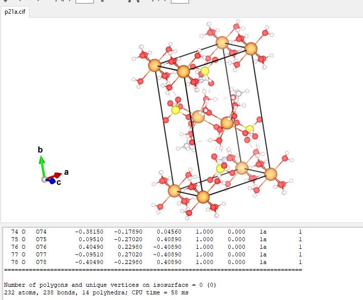
    image0 (4).jpeg

    Hope this helps,


  • Phonon density of states plotting
    aerba aerba
    Harmonic and Anharmonic Lattice Dynamics and Thermodynamics

    Hi,

    As there are different ways to compute phonons in CRYSTAL, can you share your input and output files to better understand what is computed and printed?


  • Questions on HSE06 Band‐Gap Accuracy in CRYSTAL
    aerba aerba
    Density-of-States

    Hi,

    Can you tell me if the "published reference values" you are comparing with are computational from other HSE06 implementations (if yes, which one) or experimental or computational from different functionals?

    Thanks


  • Raman CPHF restart
    aerba aerba
    Vibrational Spectroscopies: IR, Raman, INS

    Hi,

    On paper, it should be possible but we've been running some tests in the last few days before answering to your question and we have been experiencing some problems with the restart option of CPHF. We are going to run more tests and we will let you know as soon as we will have some updates.


  • How is the Fermi level computed in CRYSTAL?
    aerba aerba
    Single-Point Calculations

    Hi,

    Section 6 of Chapter 2 of this book addresses these aspects into some detail:

    Pisani, C.; Dovesi, R.; Roetti, C. Hartree-Fock Ab Initio Treatment of Crystalline solids; Lecture Notes in Chemistry Series; Springer Verlag: Berlin, 1988; Vol. 48.

    I have extracted the relevant pages here.


  • Is it necessary to add the keyword NOSYMADA when using a user-defined anisotropic k-point grid?
    aerba aerba
    Single-Point Calculations

    Hi,

    The SCF converged because at cycle 8 the energy change with respect to the previous cycle was below the default threshold of 1.0E-6:

    CYC 8 ETOT(AU) -8.392097541980E+03 DETOT 8.46E-07

    By inspection of this specific SCF, I would suggest to re-run it by tightening the convergence criterion a little, for instance with:

    TOLDEE
    8

    Hope this clarifies things a little


  • Basis Sets for Spin-Orbit
    aerba aerba
    Spin-Orbit Coupling and SCDFT

    Hi,

    In the current implementation in CRYSTAL, SOC is described through relativistic effective core pseudo-potentials (RECPs) and thus is not included if all-electron basis sets are used.

    However, there are two important points to be stressed:

    1. It is possible to run a SOC calculation where RECPs are used on a subset of elements while all-electron basis sets are used on remaining atoms (this is the case of the input file you initially shared, where you had RECPs on Pt and all-electron basis sets for Mg and Si).

    2. Some POB basis sets (i.e. those of heavy elements) do make use of RECPs that can be used for SOC calculations in CRYSTAL. These basis sets are labeled with a _SOC at the end of their name. Please, refer to this page:

    https://www.crystal.unito.it/basis_sets.htm

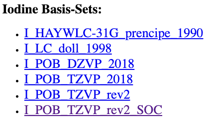
    By clicking on an element (Iodine for instance), you'll get the list of available basis sets already in CRYSTAL format:

    Screenshot 2025-04-17 alle 08.26.08.png

    In this example, the last one is a POB basis set that can be used for SOC calculations.

    Hope this helps


  • Usage of the RESTART Keyword
    aerba aerba
    Geometry Optimisations

    Hi,

    Hessian information is indeed contained in the OPTINFO.DAT file, as is information on the last geometry of the previous run so that it is indeed unnecessary to manually update the geometry in the new input.

    This is not so clear from the documentation: I had to check in the code 🙂

    Hope this clarifies things a little


  • Usage of the RESTART Keyword
    aerba aerba
    Geometry Optimisations

    Hi,

    Good to know it now works. Just for future reference, to restart a geometry optimization in CRYSTAL, the input looks like:

    OPTGEOM
    RESTART
    END
    

    In order to make this restart work, you need just a couple of files from the previous job to be placed in the scratch folder of the new job: OPTINFO.DAT, and fort.9 (to be renamed fort.20 in the new folder).


  • optimized EOS coordinates and final CVOLOPT
    aerba aerba
    Equation-of-State and Pressure

    Hi,

    Keeping in mind that geometry optimizations (unconstrained, volume-constrained, pressure-constrained) are all numerical processes with final results that thus may depend on numerical aspects of the implemented algorithms:

    1. If you are interested in the structure of the true minimum of the PES, the best way to get it is directly from an unconstrained optimization (either from an OPTGEOM calculation or from the PREOPTGEOM within the EOS). By definition, numerically, this is the geometry corresponding to the lowest energy. In both cases, the optimized structure (volume, lattice parameters, atomic positions) is printed in full.

    2. If, after an EOS calculation, you are interested in getting the structure for a specific volume V (not the minimum), then the strategy you described is exactly what I would do (and I've often done): I make sure to input a structure corresponding to the desired volume (typically by manually adjusting the lattice parameters) and I run a further CVOLOPT calculation.

    Note: During a CVOLOPT calculation the volume of the system is expected to remain almost constant (within a certain numerical error). So small variations may be observed. If instead you experience large variations, there may be a problem.


  • COHP calculations Issue
    aerba aerba
    Density-of-States

    Hi,

    Can you try to re-run the COHP calculation by using:

    COHP
    16 500 200 360  2 12  0
    

    instead of

    COHP
    16 500 200 360  1 12  0
    

    This should generate a file COHP.DAT
    Let me know how this goes.


  • Out of Memory Error during CPKS Calculation for Large System (400+ atoms)
    aerba aerba
    Single-Point Calculations

    Hi,

    The CPKS implementation in PCRYSTAL is parallelized according to a replicated-data strategy, which means that each process has a copy of the main arrays. Assume that each process (usually coinciding with each CPU core) allocates X GB of memory. If you run the job over n CPU cores in the same node, the total amount of required memory on the node will be nX.

    So, one way to reduce the memory requirement of a replicated-data calculation is to lower the number of used CPU cores per node.

    As an example, if you have a node with 128 CPU cores, try running the calculation on just 64 or 32 cores, making sure no other processes are executed on the node at the same time. This would effectively increase the available memory.

    Hope this helps.


  • Error reading end of file when visualizing Raman vibrational modes
    aerba aerba
    CRYSPLOT

    Hi,

    We have found a workaround that allows you to visualize animations of normal modes from CRYSPLOT also from a FRAGMENT calculation.

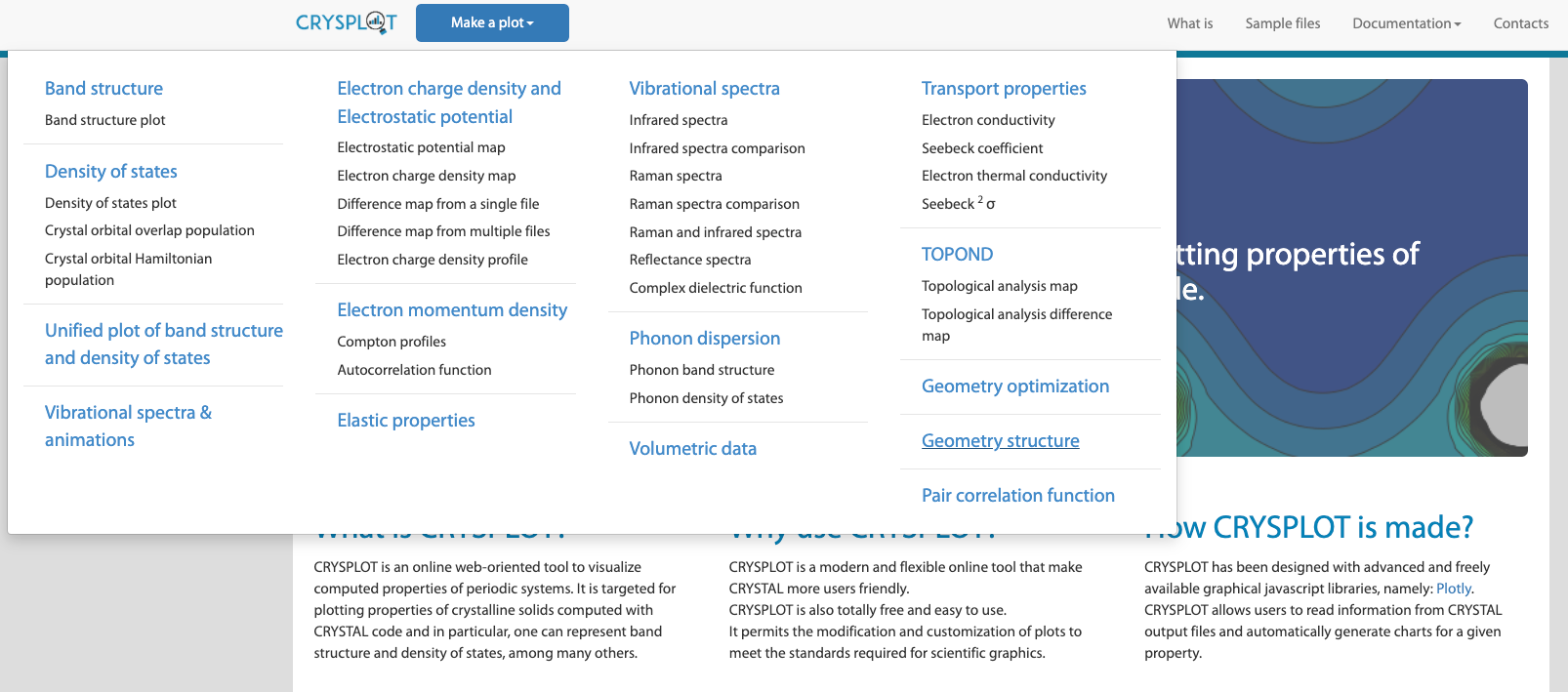
    1. Go to CRYSPLOT and from the "Make a Plot" menu select "Geometry Structure" (bottom-right)

    Screenshot 2025-04-01 alle 14.41.45.png

    1. Select and upload your output file (.out)

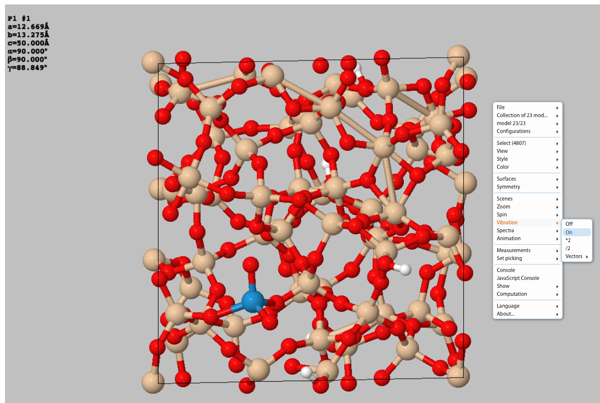
    2. By right-clicking with your mouse select "Vibration" and set it to "On":

    Screenshot 2025-04-01 alle 14.42.37.png

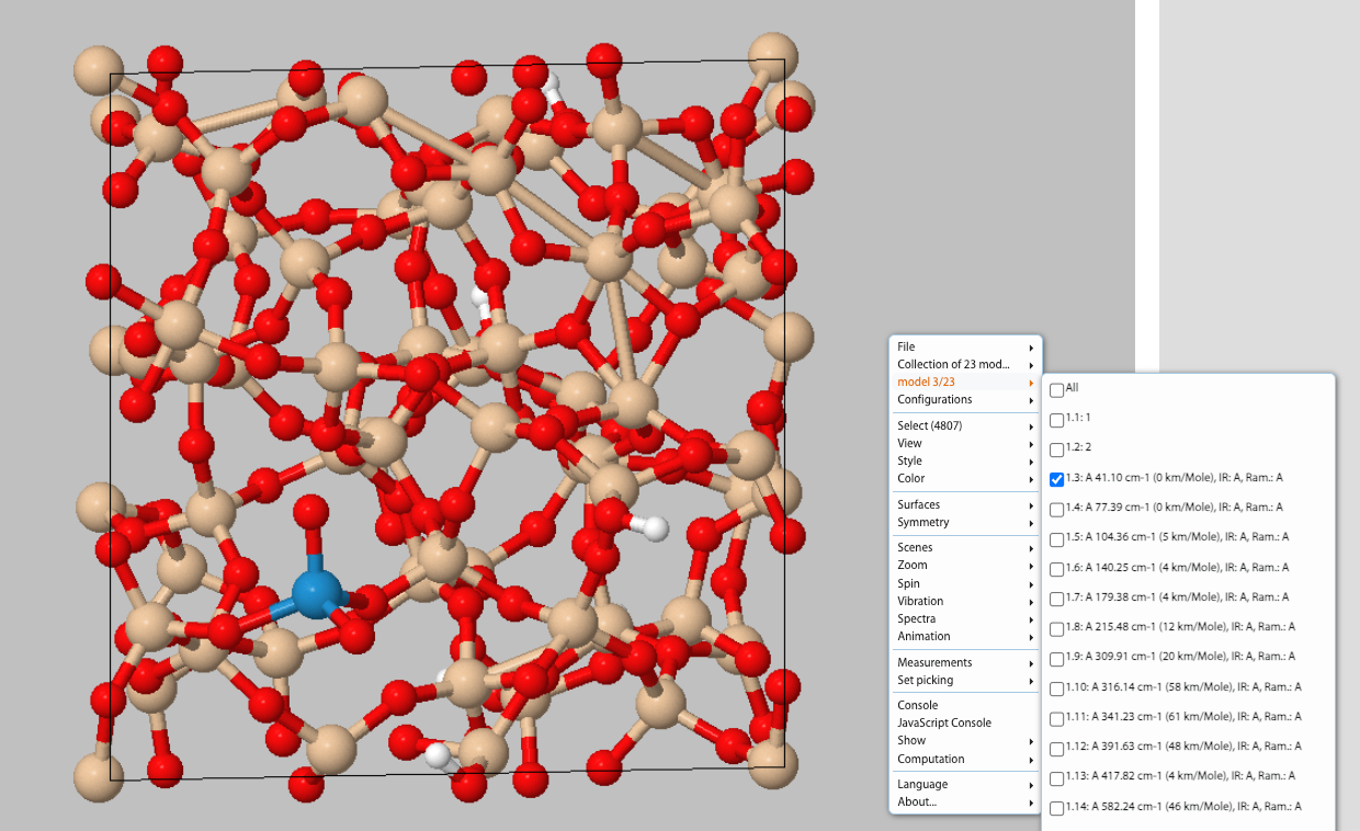
    1. At this point, by right-clicking with your mouse select "Model x/23" and select desired Mode from list to animate it:

    Screenshot 2025-04-01 alle 14.43.06.png

    Hope this helps


  • Error reading end of file when visualizing Raman vibrational modes
    aerba aerba
    CRYSPLOT

    job314 only for FRAGMENT calculations. See my reply below/above.


  • Error reading end of file when visualizing Raman vibrational modes
    aerba aerba
    CRYSPLOT

    Hi,

    We've been running some tests. This is what we found: Vibration Mode Animations on CRYSPLOT are run through JSmol, which does not seem to correctly read a CRYSTAL output file if the option FRAGMENT is used. Without FRAGMENT everything works fine.

    We could read your FRAGMENT output file and correctly visualize animations of the modes by using the MOLDRAW package instead.


  • Frequency calculation of very large systems
    aerba aerba
    Harmonic and Anharmonic Lattice Dynamics and Thermodynamics

    Hi,

    I think that the best way to proceed in this case would be to restart the calculation one or more times. To do this, you just have to make sure that the scratch folder is not deleted when the calculation stops. Basically, you would run a first job with:

    FREQCALC
    END
    

    Then, after the first calculation stops (maybe because you reached a wall clock time limit) you would run a second job restarting from the first as:

    FREQCALC
    RESTART
    END
    

    In order to make this restart work, you need a few files from the previous job to be placed in the scratch folder of the new job: FREQINFO.DAT, fort.13 and fort.9 (to be renamed fort.20 in the new folder).

    If needed, you can repeat this restart process multiple times until completion of the frequency calculation.

    Hope this helps,


  • geometry optimization runs out of cycles
    aerba aerba
    Geometry Optimisations

    Hi,

    I have looked at the code and figured out what is going on. Let me explain what is happening first. I'll then offer a solution below.

    You are running a pre-optimization within a frequency calculation + Raman intensity calculation (via the CPHF/KS approach):

    FREQCALC
    FRAGMENT
    19
    9 106 131 175 191 192 193  194 195 196 197 198 199 200 201 202 203 204 205
    PREOPTGEOM
    RESTART
    MAXCYCLE
    700
    ATOMONLY
    END
    INTENS
    INTRAMAN
    INTCPHF
    END
    END
    

    It turns out that the same variable is used in the code to define the maximum number of optimization steps and the maximum number of cycles in the CPHF/KS process. The default maximum number of cycles for CPHF/KS for intensity calculations is 200. Thus what happens is that with MAXCYCLE you set it to 700 but when the INTCPHF keyword is read it is internally re-set to the default of 200.

    Clearly, this is not ideal! We are going to fix it in future versions.

    Luckily, there is a simple workaround. Everything is fine if you run a geometry optimization first, then followed by a subsequent frequency calculation starting from the optimized geometry.

    The first calculation would look something like:

    OPTGEOM
    ATOMONLY
    MAXCYCLE
    700
    END
    

    And the second one (from the optimized geometry obtained at the previous step) would be:

    FREQCALC
    FRAGMENT
    19
    9 106 131 175 191 192 193  194 195 196 197 198 199 200 201 202 203 204 205
    INTENS
    INTRAMAN
    INTCPHF
    END
    END
    

    Hope this helps


  • Anisotropic Shrinking Factor
    aerba aerba
    Single-Point Calculations

    Hi,

    If you want to specify an anisotropic shrinking factor, the syntax in CRYSTAL is slightly different. In your case it would be:

    SHRINK
    0 0
    3 2 2
    

    Please, take in mind that the anisotropic shrinking factor in CRYSTAL does not work properly for those calculations where the symmetry of the system may change (for instance in frequency calculations, FREQCALC, where displaced nuclear configurations are explored, or elastic calculations, ELASTCON, where the lattice is strained, etc.).

    However, for symmetry-preserving calculations (such as SCF, OPTGEOM, EOS) the use of an anisotropic shrinking factor should be fine.


  • Problem in Restarting IR Intensities Calculation with CPHF
    aerba aerba
    Vibrational Spectroscopies: IR, Raman, INS

    Hi,

    Indeed, to restart an INTCPHF intensity calculation, the INTCPHF keyword must be kept.

    In your case, the restart input would look something like:

    FREQCALC
    INTENS
    INTRAMAN
    INTCPHF
    ENDCPHF
    RESTART
    ENDFREQ
    

  • Error with external electric field
    aerba aerba
    Response Properties (CPHF/KS)

    Hi,

    The two options you are using, FIELDCON and FIELD, apply a finite electric field along non-periodic and periodic directions, respectively. Thus, FIELDCON can be used for low-dimensional systems (1D, 2D) only.

    When the finite electric field is applied along a periodic direction (FIELD option), a supercell must be built along that direction, which requires additional input parameters with respect to the FIELDCON option. A complete input in your case would look something like:

    FIELD
    0.00194467
    0 0 1
    4 1
    40 1
    

    where 4 is the supercell expansion factor along the periodic direction of the field and 40 is the number of Fourier terms for the triangular potential expansion.

    For a detailed description of the use of FIELD and FIELDCON, please refer to this tutorial page.

    Note

    Please, be aware that a more analytical approach is available in CRYSTAL to compute the optical dielectric tensor of a system - that does not require any supercell to be built - through the coupled-perturbed Kohn-Sham (CPKS) method. The input for this option is simply:

    CPKS
    END
    

    to be inserted before the END of the geometry input block.

    You can find a tutorial page on CPKS here.

    We do strongly encourage to use CPKS rather than FIELD unless strictly needed.

  • 1
  • 2
  • 3
  • 4
  • 5
  • 6
  • 5 / 6
  • Login

  • Don't have an account? Register

  • Login or register to search.
  • First post
    Last post
0
  • Home
  • Recent