Skip to content

World

Topics from outside of this forum. Views and opinions represented here may not reflect those of this forum and its members.

A world of content at your fingertips…

Think of this as your global discovery feed. It brings together interesting discussions from across the web and other communities, all in one place.

While you can browse what's trending now, the best way to use this feed is to make it your own. By creating an account, you can follow specific creators and topics to filter out the noise and see only what matters to you.

Ready to dive in? Create an account to start following others, get notified when people reply to you, and save your favorite finds.

Register Login
  • Yachao_su

    Hello, I have a question regarding the use of the NOSYMADA keyword in CRYSTAL.

    While reading the CRYSTAL manual, I came across the note that “User defined anisotropic net is not compatible with SABF (Symmetry Adapted Bloch Functions). See NOSYMADA, page 122.” (page 126).

    However, I noticed that in the following example: https://wiki.aalto.fi/pages/viewpage.action?pageId=180298659, the author performed geometry optimization for Sr₅(BO₃)₃H using an anisotropic k-point grid, but did not include the NOSYMADA keyword.

    I also did a test myself: I defined an anisotropic k-point mesh (1×5×5) and did not use NOSYMADA. In the .out file, I still see the line:
    “NUMBER OF SYMMETRY OPERATORS : 2”,
    which suggests that symmetry was not automatically disabled despite using an anisotropic grid.

    So my question is:
    When using a user-defined anisotropic k-point grid in CRYSTAL, is it necessary to explicitly include the NOSYMADA keyword?


    Your response is incredibly valuable—thank you so much.I suspect that the DIIS/Anderson extrapolation might have 'hit' a local minimum, so the density guess in iteration 8 happened to yield a total energy extremely close to that of the previous step, resulting in a very small ΔE. CYC 0 ETOT(AU) -8.456120523718E+03 DETOT -8.46E+03 tst 0.00E+00 PX 1.00E+00 CYC 1 ETOT(AU) -8.390242659622E+03 DETOT 6.59E+01 tst 0.00E+00 PX 1.00E+00 CYC 2 ETOT(AU) -8.391027170997E+03 DETOT -7.85E-01 tst 3.34E-03 PX 1.13E-01 CYC 3 ETOT(AU) -8.391734802465E+03 DETOT -7.08E-01 tst 2.44E-03 PX 1.02E-01 CYC 4 ETOT(AU) -8.392064543836E+03 DETOT -3.30E-01 tst 8.38E-04 PX 4.49E-02 CYC 5 ETOT(AU) -8.392086825687E+03 DETOT -2.23E-02 tst 1.24E-04 PX 1.72E-02 CYC 6 ETOT(AU) -8.392095974656E+03 DETOT -9.15E-03 tst 2.86E-05 PX 9.66E-03 CYC 7 ETOT(AU) -8.392097542826E+03 DETOT -1.57E-03 tst 3.85E-06 PX 4.81E-03 CYC 8 ETOT(AU) -8.392097541980E+03 DETOT 8.46E-07 tst 5.41E-06 PX 3.18E-03 CYC 9 ETOT(AU) -8.392098065539E+03 DETOT -5.24E-04 tst 4.69E-06 PX 3.18E-03 While this DETOT value satisfies the default energy convergence criterion, the corresponding values suggest that the electron density had not yet fully stabilized. This aligns well with your suggestion that tightening the convergence threshold would lead to a more reliable result. Thank you again for your guidance.
  • Yachao_su
    This post is deleted!

    Many thanks for your detailed explanation and for checking the code — that definitely clarifies things. I really appreciate your help!
  • Gryffindor

    Hi,

    I am performing DOS calculations on systems that include guest molecules (in this case, methanol) inside a framework. While the calculation finishes and produces a DOSS.DAT file that appears valid when plotted with crysplot, the output ends with an error.

    This behavior is consistent across multiple systems involving different guest species, while pure framework-only calculations proceed without issue. It seems like the error might be related to the atom indices used for projected DOS when guest molecules are included. I have attached the input and output files below. Can you please help me with it?

    INPUT.txt

    OUTPUT.txt


    Oh yes, right. My apologies. I did not notice this. Thank you Giacomo!
  • masoud37

    Dear Colleagues,

    I am trying to compute the total COHP for a system containing 20 atoms, including four different elements. Although I have included all bonds in the input file, the output file appears to contain DOS instead of COHP.

    I have attached both the input and output files for reference. I would greatly appreciate any guidance on how to obtain the correct COHP for my system.

    Best regards,
    Masoud
    COHP.DAT INPUT.d12


    Hi, Can you try to re-run the COHP calculation by using: COHP 16 500 200 360 2 12 0 instead of COHP 16 500 200 360 1 12 0 This should generate a file COHP.DAT Let me know how this goes.
  • Gryffindor

    Hi,

    I'm trying to run a CPKS calculation on a system with 400+ atoms, but the job keeps getting aborted due to out of memory (OOM) issues. I'm using 200 GB as the maximum memory limit per job (which is also the maximum allowed on our cluster), but the calculation still fails with OOM errors.

    Is there anything I can do to reduce the memory load during the CPKS step (e.g., approximations, splitting into smaller jobs, etc.)?
    I tried using LOWMEM, but it did not help.
    INPUT.dat

    OUTPUT.dat


    Hi Alessandro and Giacomo, Thank you for the clear and helpful explanations! I tried running the calculation with 32 cores, and it indeed helped with memory management. I’ll continue experimenting to optimize performance. Really appreciate your guidance and the references!
  • job314

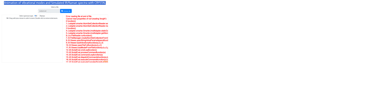
    Having problems here:

    Animation of vibrational modes and Simulated IR/Raman spectra with CRYSTAL

    Untitled.png

    This is the output.out output file


    you're the best, thank you for going extra mile
  • job314

    I am getting into a strange error where R2SCAN keyword is not recognized whereas I used it in similar systems many times. Theo only difference is this one UHF - is it not available in UHF?

      52 H   -2.071   7.445  -3.437
     INFORMATION **** SET_MPP **** PCRYSTAL CALCULATION
     INFORMATION **** READM2 **** NEW DEFAULT: FOCK/KS MATRIX MIXING SET TO 30 %
     INFORMATION **** READM2 **** NEW DEFAULT: FULL DIRECT SCF MODE
     INFORMATION **** READM2 **** NEW DEFAULT: COULOMB BIPOLAR BUFFER SET TO 32 Mb
     INFORMATION **** READM2 **** NEW DEFAULT: EXCHANGE BIPOLAR BUFFER SET TO 32 Mb
     INFORMATION **** UHF **** SPIN POLARIZED SOLUTIONS ALLOWED
    
     *******************************************************************************
     NEW DEFAULT: DFT INTEGRATION GRID INCREASED TO XLGRID
     NEW DEFAULT: DIIS ACCELERATOR ACTIVE
     USE KEYWORD NODIIS TO TURN IT OFF
     *******************************************************************************
    
     ERROR **** RDDFTP **** KEYWORD R2SCAN       NOT RECOGNIZED
     TTTTTTTTTTTTTTTTTTTTTTTTTTTTTT ERR         TELAPSE        2.03 TCPU        0.00
    

    input_r2scan.d12


    Thank you very much, that worked (but not restart)
  • Gryffindor

    Hello,

    I am currently working on calculating the response properties and density of states (DOS) for a spin-polarized system involving Cobalt, ZIF-9. To familiarize myself with the process, I conducted a small SCF test calculation. Despite specifying an increased number of SCF cycles, the calculation consistently terminates after 50 steps without achieving convergence.

    I have referred to the CRYSTAL tutorials on SCF convergence tools and magnetic systems . However, I am still encountering the same problem. Could you kindly look into the input and output and let me know what might be going wrong, which keywords could I use?

    Thanks

    INPUT.d12.txt

    OUTPUT.d12.txt


    Dear Eleonora and Aleks, Thank you so much for the detailed explanation and for sharing the corrected input/output file. That really clarified the issue. I tried your suggested settings with FMIXING and SPINLOCK adjustments, and the geometry optimization is running well with no errors. Have a nice day! Best, Aparajita
  • jquertin

    Hi all,
    I'm working on large unit cells (300+ atoms).
    With the computational resources that I have, I cannot run the frequency calculation "reasonably".
    Does anyone knows if there would be a trick such as running subsequent calculation using restarts and fragments of increasing size? Or even better, having multiple calculations with different parts of the cell and bringing them all together for the thermodynamics?
    Thanks in advance,
    Jean


    Hi, I think that the best way to proceed in this case would be to restart the calculation one or more times. To do this, you just have to make sure that the scratch folder is not deleted when the calculation stops. Basically, you would run a first job with: FREQCALC END Then, after the first calculation stops (maybe because you reached a wall clock time limit) you would run a second job restarting from the first as: FREQCALC RESTART END In order to make this restart work, you need a few files from the previous job to be placed in the scratch folder of the new job: FREQINFO.DAT, fort.13 and fort.9 (to be renamed fort.20 in the new folder). If needed, you can repeat this restart process multiple times until completion of the frequency calculation. Hope this helps,
  • job314

    I noticed that MAXCYCLE keyword does not work very well in optimization. I had the same problem with EOS - it runs out of arbitrary number of cycles nevermind I specify MAXCYCLE as a large number.

    Simple geometry optimization of a large cell, restarted, with MAXCYCLE 700 stops after 200 cycles - I am sure logical reason for it exists, perhaps you can advise?

    PREDICTED ENERGY CHANGE -0.366E-07

    MAX GRADIENT 0.000036 THRESHOLD 0.000045 CONVERGED YES
    RMS GRADIENT 0.000005 THRESHOLD 0.000030 CONVERGED YES
    MAX DISPLAC. 0.000921 THRESHOLD 0.000180 CONVERGED NO
    RMS DISPLAC. 0.000167 THRESHOLD 0.000120 CONVERGED NO
    CONVERGENCE TESTS UNSATISFIED AFTER 200 ENERGY AND GRADIENT CALCULATIONS


    • OPT END - FAILED * E(AU): -2.756455928711E+04 POINTS 200 *

    INPUT (2).d12 Input and output.out output


    thank you
  • job314

    Raman calculations, restarting for spectral calculation returns this error; see the files and thank you (system does not allow to upload majority of the file formats, unfortunately, including FREQINFO.DAT)TENS_RAMAN.DAT INPUT.d12 output.out [fort.34](Invalid file type. Allowed types are: .png, .jpg, .bmp, .txt, .gif, .d12, .out, .dat, .d3, .outp, .input, .output, .jpeg) fort.dat


    very grateful, I will run it again but not sure what to do here if it aborts again
  • ywang

    Dear Crystal users and developers,

    I am using CRYSTAL17 to calculate 3D structures, it is successful in running the program for the majority of structures. But for some structures, the program ended without error, and the final information is:

    INFORMATION **** SET_MPP **** PCRYSTAL CALCULATION
    INFORMATION **** READM2 **** NEW DEFAULT: FOCK/KS MATRIX MIXING SET TO 30 %
    INFORMATION **** READM2 **** NEW DEFAULT: FULL DIRECT SCF MODE
    INFORMATION **** READM2 **** NEW DEFAULT: COULOMB BIPOLAR BUFFER SET TO 32 Mb

    can anyone let me know how to fix this problem, thank you in advance.

    All the best,
    wang


    @GiacomoAmbrogio Dear Ambrogio, Thank you so much! the problem has been perfectly solved. All the best, wang
  • Gryffindor

    I'm modeling ZIF-1 with lattice parameters:
    (a, b, c) = 9.9561 15.1037 15.047
    (alpha, beta, gamma) = 90.00 98.221 90.003

    Despite specifying SHRINK 3 2 2 for an SCF calculation, the output shows isotropic shrinking factors (3 3 3). Why is CRYSTAL23 not applying the anisotropic factors as input? Are there additional settings required for anisotropic k-point meshes in low-symmetry MOFs? Any insights on resolving this discrepancy would be really helpful.

    7d80b07c-146a-42aa-a627-de4e18931ef3-image.png

    626539d2-6914-40b0-9799-63796114563c-image.png


    Hey, Thank you. It works now. This Forum is a great idea!
  • GiacomoAmbrogio

    Dear CRYSTAL community,

    We’re excited to share our recent work on accelerating linear algebra operations in the CRYSTAL code using GPUs. Our implementation boosts the performance of self-consistent field (SCF) calculations by offloading key matrix operations like multiplication, diagonalization, inversion, and Cholesky decomposition to GPUs.

    In the manuscript, we first analyze the performance and limitations of the standard parallel version of the code (Pcrystal) and then we evaluate the scalability of the new GPU-accelerated approach with 1 to 8 GPUs, observing remarkable scaling. To highlight these improvements, we present benchmark results on different systems, such as the example below.

    post_forum_1.png

    We expected significant speedups for large systems due to the limited number of k points, each requiring substantial computational effort. To ensure a fair comparison, we ran calculations using the massively parallel version of CRYSTAL (MPPcrystal) on a large MOF structure with over 30000 basis functions. Surprisingly, a single GPU on one node performed comparably to 512–1024 CPU cores running across 4–8 nodes.

    To find out more, read the full paper here.

    We aim to make this GPU-accelerated version of CRYSTAL available in the upcoming release, allowing all users to benefit from its enhanced performance for large-scale simulations. We look forward to reading your thoughts and discussing potential applications or further improvements.

    A big thanks to Lorenzo Donà, Chiara Ribaldone, and Filippo Spiga for their contributions to the development of this code!


  • job314

    I found this forum very useful and very informative. I would like to ask help with Raman spectra calculation interpretation. We normally run 532 nm Raman on our powders and I would like to calculate said spectrum. However, I find it difficult as I view through the calculation output to find out which one is which. In particular, first I run

    EXTERNAL    
    FREQCALC
    FRAGMENT
    10
    9 106 131 175 191 192 193  194 195 196 197
    PREOPTGEOM
    ATOMONLY
    END
    INTENS
    INTRAMAN
    INTCPHF
    END
    END
    END
    

    and obtain Raman.out this output. This provides these modes

       27-  27    0.1614E-04    881.8618   26.4376  (A  )   A (  1850.51)   A
       28-  28    0.1776E-04    925.0155   27.7313  (A  )   A (   528.78)   A
       29-  29    0.1840E-04    941.4794   28.2248  (A  )   A (   120.15)   A
       30-  30    0.2223E-04   1034.8768   31.0248  (A  )   A (    89.10)   A
    

    then polycrystalline

       27-  27      881.8618 (A  )     48.11     27.86     20.26
       28-  28      925.0155 (A  )    198.27    175.12     23.16
       29-  29      941.4794 (A  )    571.74    518.42     53.32
       30-  30     1034.8768 (A  )   1000.00    947.97     52.03
    

    and crystalline printouts

       27-  27      881.8618 (A  )    8.45   24.41   40.44    9.34    6.13   11.78
       28-  28      925.0155 (A  )  120.61   24.34    1.57  214.59   57.50   53.57
       29-  29      941.4794 (A  )   51.70   47.91   33.81  449.39   12.69  878.42
       30-  30     1034.8768 (A  )  949.93   32.47   88.71 1000.00   45.46  356.43
    

    At this point I am lost as I am not sure which ones CRYSPLOT extracts.
    Then I try to obtain those for 532 nm laser so I restart with

    EXTERNAL    
    FREQCALC
    RESTART
    FRAGMENT
    10
    9 106 131 175 191 192 193  194 195 196 197
    INTENS
    INTRAMAN
    RAMANREA
    RAMEXP
    295. 532.
    ENDFREQ
    END
    

    but in the file I obtain it is pretty much the same information Ramexp.out

    
       27-  27    0.1614E-04    881.8618   26.4376  (A  )   A (  1850.51)   A
       28-  28    0.1776E-04    925.0155   27.7313  (A  )   A (   528.78)   A
       29-  29    0.1840E-04    941.4794   28.2248  (A  )   A (   120.15)   A
       30-  30    0.2223E-04   1034.8768   31.0248  (A  )   A (    89.10)   A
    [...]
    <RAMAN><RAMAN><RAMAN><RAMAN><RAMAN><RAMAN><RAMAN><RAMAN><RAMAN><RAMAN><RAMAN>
    [...]
       27-  27      881.8618 (A  )     42.48     24.60     17.89
       28-  28      925.0155 (A  )    164.88    145.62     19.26
       29-  29      941.4794 (A  )    465.01    421.64     43.37
       30-  30     1034.8768 (A  )    721.86    684.30     37.56
    [...]
       27-  27      881.8618 (A  )    4.11   11.87   19.67    4.54    2.98    5.73
       28-  28      925.0155 (A  )   55.23   11.14    0.72   98.27   26.33   24.53
       29-  29      941.4794 (A  )   23.15   21.46   15.14  201.27    5.68  393.41
       30-  30     1034.8768 (A  )  377.60   12.91   35.26  397.50   18.07  141.68
    [...]
     <RAMAN><RAMAN><RAMAN><RAMAN><RAMAN><RAMAN><RAMAN><RAMAN><RAMAN><RAMAN><RAMAN>
    

    I think I am after one of these below but I am simply not sure what CRYSPLOT is plotting or which ones are written into RAMSPEC.DAT (and what is the difference between first and second run, honestly).

    I was wondering if somebody could read this long email, look at the two files and elaborate a little on these results since all the Raman vibrations are plotted at least thrice in each file.


    Dear Jonas, Thanks for reaching out and being one of the most active users of these early days of the forum. Your question gives us the chance to clarify some aspects of the output file that might not be obvious to non expert users. Below, I will refer to your output file. Harmonic Frequencies and IR intensities To compute harmonic frequencies and IR intensities (with the default approach of the Berry phase) the input looks like: FREQCALC INTENS ENDFREQ In the output file, the following table is printed: HHHHHHHHHHHHHHHHHHHHHHHHHHHHHHHHHHHHHHHHHHHHHHHHHHHHHHHHHHHHHHHHHHHHHHHHHHHHHH EIGENVALUES (EIGV) OF THE MASS WEIGHTED HESSIAN MATRIX AND HARMONIC TRANSVERSE OPTICAL (TO) FREQUENCIES. IRREP LABELS REFER TO SYMMETRY REPRESENTATION ANALYSIS; A AND I INDICATE WHETHER THE MODE IS ACTIVE OR INACTIVE, RESPECTIVELY, FOR IR AND RAMAN; INTEGRATED IR INTENSITIES IN BRACKETS. CONVERSION FACTORS FOR FREQUENCIES: 1 CM**(-1) = 0.4556335E-05 HARTREE 1 THZ = 0.3335641E+02 CM**(-1) HHHHHHHHHHHHHHHHHHHHHHHHHHHHHHHHHHHHHHHHHHHHHHHHHHHHHHHHHHHHHHHHHHHHHHHHHHHHHH MODES EIGV FREQUENCIES IRREP IR INTENS RAMAN (HARTREE**2) (CM**-1) (THZ) (KM/MOL) 1- 1 0.3488E-07 40.9894 1.2288 (A ) A ( 0.40) A 2- 2 0.6077E-07 54.1037 1.6220 (A ) A ( 0.96) A 3- 3 0.6801E-07 57.2344 1.7158 (A ) A ( 2.45) A 4- 4 0.2238E-06 103.8371 3.1130 (A ) A ( 11.47) A For each mode (or set of degenerate modes) its eigenvalue (in Ha\(^2\)), harmonic frequency (in cm\(^{-1}\) and THz) and irreducible representation get printed. In addition, labels specifying whether the mode is IR/Raman active are also displayed (A and I indicate whether the mode is active or inactive, respectively). Raman intensities Raman intensities can be computed via a coupled-perturbed approach by inserting the INTRAMAN keyword followed by the INTCPHF block in the input deck: FREQCALC INTRAMAN INTCPHF END ENDFREQ Raman intensities are computed for each independent component of the polarizability tensor (xx, xy, xz, yy, yz, zz, labeled as "Single Crystal" in the output file) and are also averaged to mimic polycrystalline powder samples (total, parallel polarisation, perpendicular polarisation averages are printed in the output). POLYCRYSTALLINE ISOTROPIC INTENSITIES (ARBITRARY UNITS) MODES FREQUENCIES I_tot I_par I_perp ---------------------------------------------------------------- 1- 1 40.9894 (A ) 0.46 0.27 0.19 2- 2 54.1037 (A ) 7.35 4.23 3.12 3- 3 57.2344 (A ) 12.79 8.82 3.96 4- 4 103.8371 (A ) 13.66 7.89 5.77 SINGLE CRYSTAL DIRECTIONAL INTENSITIES (ARBITRARY UNITS) MODES FREQUENCIES I_xx I_xy I_xz I_yy I_yz I_zz ---------------------------------------------------------------------------- 1- 1 40.9894 (A ) 0.00 0.37 0.02 0.63 0.00 0.21 2- 2 54.1037 (A ) 3.17 0.69 0.00 4.35 3.66 10.05 3- 3 57.2344 (A ) 3.82 3.54 0.02 3.50 0.03 27.53 4- 4 103.8371 (A ) 2.57 1.81 0.01 16.25 3.34 19.62 For more details on such polycrystalline averages, please refer to sections 8.4 and 8.7 of the CRYSTAL23 manual. Raman spectrum A continuous Raman spectrum can be simulated by use of the RAMSPEC block, as in: FREQCALC INTRAMAN INTCPHF END RAMSPEC END ENDFREQ The simulated spectrum is printed in an external file named RAMSPEC.DAT that contains several columns: column 1 with frequencies in cm\(^{-1}\), columns 2-4 with polycrystalline intensities (total, parallel, perpendicular), columns 5-10 with single crystal intensities (xx, xy, xz, yy, yz, zz). Effect of Temperature and Laser wavelength The effect of temperature and laser wavelength on computed Raman intensities can be accounted for by use of the RAMANEXP keyword, as in: FREQCALC INTRAMAN INTCPHF END RAMANEXP 298 532 RAMSPEC END ENDFREQ Here we set 298 K for the temperature and 532 nm for the laser wavelength. This option modifies the values of all computed Raman intensities (in the output and in the RAMSPEC.DAT file accordingly). Please, note that other properties (harmonic frequencies and IR intensities) are not affected by this option and thus remain unchanged in the output. Plots When CRYSPLOT reads the CRYSTAL output file it only plots the total intensity of the polycrystalline powder model. When CRYSPLOT reads the RAMSPEC.DAT file it plots all components: [image: Screenshot 2025-03-13 at 12.47.37.png] Other plotting tools can be used to plot specific columns of the RAMSPEC.DAT file (e.g., CRYSTALClear, gnuplot).
  • xrocquef

    I now have one more problem during the next step, which consists to restart the calculation to obtain the Raman spectrum. In my previous calculations using CPHF I was using the sequence:

    FREQCALC
    RESTART
    INTENS
    DIELTENS
    5.30029   -0.00000   -0.00000
    0.00000    5.30029   -0.00000
    0.00000   -0.00000    5.30029
    IRSPEC
    DAMPFAC
    5.0
    GAUSS
    ENDIR
    ENDFREQ
    

    and it was working perfectly, but here I have the following error message:

    RESTART FROM  AN INCOMPLETE HESSIAN MATRIX
    ERROR **** RESTHES **** RESTART DATA WAS OBTAINED WITH CPHF, USE INTCPHF
    

    Is it possible that the RESTART when using NOINTSYM in the INTCPHF block must be different? I didn't find any lines about NOINTSYM in the USERGUIDE.
    Best regards

    Xavier


    Thank you very much Jacques and Alessandro. Now it works :). Best regards Xavier
  • masoud37

    Dear Colleagues,
    I hope you're doing well.
    I have a question regarding an error I encountered in my calculations using CRYSTAL17 and would appreciate your help.

    I attempted to apply an external electric field in the 0-0-1 direction to a bulk structure using the following keywords in my input file:

    FIELD
    0.00194467
    0 0 1

    However, I received a syntax error. Please see the attached input input and output files.

    Previously, I successfully applied an external electric field to 2D nanostructures using the "FIELDCON" keyword without any issues. However, I encountered this error when working with bulk structures.
    I would be grateful for any guidance you can provide.

    Best regard,
    Masoud


    Hi, Thank you very much for your reply! Best regards, Masoud
  • xrocquef

    Dear Colleagues,
    I am running a CPHF calculation and I have a MPI crash which I do not really understand. In the file fort.87 I have the following error message:
    ERROR **** SHELLXNhi_task **** UNABLE TO FIND G' IN NQGSHG
    If needed I can provide my input file.
    Best regards
    Xavier


    Dear Jacques, Thank you for your reply which indeed solve the problem. Best regards Xavier
  • R.Zosiamliana

    Dear Crystal users and developers,

    I am currently working in the investigation of 3D bulk to 2D surface slab properties.

    I actually do not understand when we create 2D surface slabs using SLABCUT keyword, whether the surface slab is directly a free standing slab(i.e.,non-periodic slab with periodicity breaking along the out of plane direction), or it is periodic slab and to break the periodicity we need to create vaccuum along c-axis..

    Here is an example of my input geometry:

    
    SLABCUT
    0 0 1
    1     7
    [...]
    

    Since, the in the output z-axis lattice constant is given as 500Angstom.

    PS: If it is periodic slab then can anyone guide me to create vaccuum in the c-axis from the input....

    Best wishes,
    R.Zosiamliana
    PSRC
    Pachhunga University College


    Thank you Giacomo Ambrogio. I am greatful to the CRYSTAL code forum This will help alot. Best Wishes
  • job314

    I suppose I have to report this here even though I have been interacting with CRYSTAL support directly. most if not all EOS cases just stop/abort with cryptic messages at the end of all of the iterations, sometimes already into EOS calculation.

    TOTAL ENERGY(DFT)(AU)(  2) -1.0219660133484E+04 DE 2.2E-09 tester 2.1E-13
    TTTTTTTTTTTTTTTTTTTTTTTTTTTTTT EDFT        TELAPSE   143507.65 TCPU   142271.40
    corrupted size vs. prev_size while consolidating
    corrupted double-linked list
    

    or

    SORTING VOLUMES/ENERGIES
    
        VOLUME (A^3)    ENERGY (a.u.)
    
        810.125802   -1.023662022986E+04
        829.558185   -1.023663933122E+04
        849.094033   -1.023665162912E+04
        868.935234   -1.023665780851E+04
        880.846516   -1.023665872507E+04
        889.065728   -1.023665819061E+04
        909.486571   -1.023665312286E+04
        930.215794   -1.023664308419E+04
        951.267331   -1.023662850026E+04
    corrupted size vs. prev_size
    corrupted size vs. prev_size
    munmap_chunk(): invalid pointer
    corrupted double-linked list
    corrupted size vs. prev_size
    munmap_chunk(): invalid pointer
    munmap_chunk(): invalid pointer
    munmap_chunk(): invalid pointer
    munmap_chunk(): invalid pointer
    munmap_chunk(): invalid pointer
    munmap_chunk(): invalid pointer
    munmap_chunk(): invalid pointer
    munmap_chunk(): invalid pointer
    munmap_chunk(): invalid pointer
    munmap_chunk(): invalid pointer
    munmap_chunk(): invalid pointer
    munmap_chunk(): invalid pointer
    munmap_chunk(): invalid pointer
    munmap_chunk(): invalid pointer
    munmap_chunk(): invalid pointer
    

    thank you