Skip to content

World

Topics from outside of this forum. Views and opinions represented here may not reflect those of this forum and its members.

A world of content at your fingertips…

Think of this as your global discovery feed. It brings together interesting discussions from across the web and other communities, all in one place.

While you can browse what's trending now, the best way to use this feed is to make it your own. By creating an account, you can follow specific creators and topics to filter out the noise and see only what matters to you.

Ready to dive in? Create an account to start following others, get notified when people reply to you, and save your favorite finds.

Register Login
  • andrejsc

    Hello!
    I am struggling to understand the way in which CRYSTAL rotates the atoms. Here is my structure:
    reference.f34
    I want to rotate all atoms so that Mn remains in place, and oxygens NN 21&23 move to the ac (xz) plane. This, in essence, is a rotation around the axis 10Mn-12P, the result of which should be that
    Y coordinate of Mn = Y(O21) = Y(O23). The angle that should work is +-24.7159 degrees, depending on the direction that CRYSTAL uses.
    So, I tried

    ATOMROT
    0 # include all atoms
    999 1 # no translation & rotation around a specified axis
    10 12 # atom labels that define rotation axis
    +/-24.7159 # angle (degrees)
    

    To the effect of

    ALL THE  36 ATOMS IN THE REFERENCE CELL ARE MANIPULATED
    
    SELECTED ATOMS ARE ROTATED AROUND THE AXIS DEFINED BY TWO ATOMS:  10  12
    (DIRECTION COSINES  0.000  0.000 -1.000) BY AN ANGLE:  24.72
    
    ATOM  10 AT.N.  25 COORDINATES   4.46889   0.00000   2.24246
    ATOM  21 AT.N.   8 COORDINATES  -2.74300   2.67751   3.17915
    ATOM  23 AT.N.   8 COORDINATES   3.56177   1.05955   3.17915
    

    and

    ALL THE  36 ATOMS IN THE REFERENCE CELL ARE MANIPULATED
    
    SELECTED ATOMS ARE ROTATED AROUND THE AXIS DEFINED BY TWO ATOMS:  10  12
    (DIRECTION COSINES  0.000  0.000 -1.000) BY AN ANGLE:  -24.72
    
    ATOM  10 AT.N.  25 COORDINATES   4.46889   0.00000   2.24246
    ATOM  21 AT.N.   8 COORDINATES  -2.25530  -3.73706   3.17915
    ATOM  23 AT.N.   8 COORDINATES   3.07407   0.00001   3.17915
    

    So the second method maybe worked? Except that I have been unable to visualize/confirm it using VESTA, because the output of edited geometry section looks the same as the input*.

    So, my questions are:

    1. how to validate the result of rotation?
    2. when using ROTCRY+MATROT, where is the origin of rotation?
    3. which method of rotation I should use in this situation?

    *VESTA, of course, does not open .f34 files, so my usual workflow is to convert CRYSTAL output to a VASP-POSCAR format:

    Structure description line
    1.0 #scaling factor
    [DIRECT LATTICE VECTORS CARTESIAN COMPONENTS (ANGSTROM)]
    List-of-elements
    Amounts-of-each-element
    Direct or Cartesian # coordinate format
    [list of coordinates in the selected format]

    

    Poking further, since the last error is that of MPI and not of CRYSTAL, I launched the same input with NEWK 8 8 as a single-core process (with Pproperties), and this time the error was different: 85-C( 3 2 4) 86-C( 4 2 4) 87-C( 5 2 4) 88-C( 3 3 4) 89-C( 4 3 4) 90-R( 4 4 4) ERROR **** PROJVR **** NULL COMPONENT 0.222045E-15 0.100000E-07 for ROTREF ATOMS 10 # this is Manganese 0 0 0 # I also tried this with different cell indices 12 # P5 0 0 0 8 # P2 0 0 0 and then 85-C( 3 2 4) 86-C( 4 2 4) 87-C( 5 2 4) 88-C( 3 3 4) 89-C( 4 3 4) 90-R( 4 4 4) ERROR **** RHOLSK **** BASIS SET LINEARLY DEPENDENT for the following input: ROTREF ATOMS 10 1 0 0 12 1 0 1 8 1 1 0 As well as for other indices
  • JohnKendrick

    Hi,

    I am doing a frequency with intensities calculation on an Iron complex with four Fe atoms in the unit cell. I am trying to do the ferromagnetic state with HSE06-D3 functional and the POB-tzvp-rev2 basis. I have optimised the cell, copied the optimised cell to fort.34 and copied the fort.9 file of the optimised calculation to fort.20, ready for a frequency calculation with intensities.

    The calculation is being run on 24 cores on a single node, with up to 4GBs of memory /core. The run uses intel mpi for interprocess communication.

    After reporting the hyperpolarisability and electric susceptibility tensors (Beta and Chi), the program crashes with:

    COMPUTING IR TENSOR ALONG DIRECTION X
    forrtl: severe (67): input statement requires too much data, unit 2, file /mnt/scratch/chmjke/SpinCrossover/CRYSTAL/HSE06/AFM2/fort.2.pe15
    

    I attach the input file: frequencies.d12
    A tar file of the output and fort.34: info.tgz

    Any help would be grateful received.
    Thanks John


    @JohnKendrick I have had the same problem in a slightly different task. I have found a solution, but it may not work for your particular task: I have reduced the number of k-points. I am modelling Mn5+ ion in a AlPO4 cell in which one P is replaced by Mn. My input is EXTERNAL FREQCALC ANALYSIS INTENS INTRAMAN INTCPHF END END BASISSET POB-TZVP-REV2 DFT WC1LYP SPIN END EXCHSIZE 44000000 BIPOSIZE 44000000 SHRINK 6 6 TOLINTEG 9 9 9 12 20 MAXCYCLE 400 TOLDEE 10 SPINLOCK 2 -6 ATOMSPIN 1 10 1 SLOSHING END The same input with SHRINK 8 8 Produced the same error as yours, regardless of convergence tools (DIIS / NODIIS (in CPHF block) / buffer sizes / etc): ELECTRIC FIELD APPLIED ALONG CARTESIAN DIRECTIONS XX [some lines omitted] BECKE WEIGHT FUNCTION RADSAFE = 2.00 TOLERANCES - DENSITY:10**- 6; POTENTIAL:10**- 9; GRID WGT:10**-14 RADIAL INTEGRATION - INTERVALS (POINTS,UPPER LIMIT): 1( 75, 4.0*R) ANGULAR INTEGRATION - INTERVALS (ACCURACY LEVEL [N. POINTS] UPPER LIMIT): 1( 4[ 86] 0.2) 2( 8[ 194] 0.5) 3( 12[ 350] 0.9) 4( 16[ 974] 3.5) 5( 12[ 350]9999.0) TTTTTTTTTTTTTTTTTTTTTTTTTTTTTT MOQGAD TELAPSE 7695.33 TCPU 7664.63 forrtl: severe (67): input statement requires too much data, unit 81, file /scratch/tmp_p267436_student/fort.81.pe11 All running on a single machine: Dell EMC C6400 Server (2x20-Core Intel XEON Gold 6148 2.40GHz, 192GB RAM, 3x480GB SSD).
  • JackClegg

    Dear All,

    I'm looking at upgrading to crystal23 but in the meantime has anyone had success in compiling from objects on an apple silicon system? I was thinking of using brew installed openmpi.

    Does anyone have a suitable include file?

    Jack


    Hi Jack, compiling from objects on Apple Silicon is possible, but there are two critical requirements: You must use OpenMPI built with the same GNU Fortran version used to compile the object files (in particular gfortran 12.1) You must use the MPI compiler wrappers (mpif90, mpicc, mpicxx) instead of the plain compilers for the final linking stage The default include file is almost correct. The only necessary changes are the compiler definitions. Replace the first lines with: F90 = mpif90 LD = $(F90) PLD = mpif90 Keep the rest unchanged. Important notes The OpenMPI you use must be built against gfortran 12.1. You can check with: mpif90 --show or mpif90 --version and verify that it points to gfortran-12. Do not mix different GNU Fortran versions (e.g. gfortran 13 or Apple clang). A mismatch here is the most common cause of runtime failures.
  • JackClegg

    Dear All,
    I have successfully run the serial version of test11. When I swap to the parallel version, however, I get the following errors:
    SCF abnormal end - no wf written in fort.9
    ls: No match.
    ls: No match.
    ls: No match.

    The full output is:

    ~ [jack] Squirrel? ~>runPcry23 8 test11
    output data in /Users/jack/test11.out
    mpirun executable in /opt/homebrew/Cellar/open-mpi/5.0.9/bin
    Pcrystal executable in /Users/jack/Code/CRYSTAL23/bin/v1.0.1
    input data in /Users/jack/Code/CRYSTAL23/test_cases/inputs/test11.d12
    file machines.LINUX in /Users/jack/Code/CRYSTAL23/utils23
    list of nodes in /Users/jack/Code/CRYSTAL23/utils23/nodes.par
    creating temporary directories /Users/jack/tmp/tmp_p84659_jack on each node
    ([email protected]) Password:
    temporary dir created on d-i184-6-123.staff.eduroam.uq.edu.au
    copying Pcrystal executable on each node
    ([email protected]) Password:
    copying input file on each node
    ([email protected]) Password:
    Pcrystal job running in /Users/jack/tmp/tmp_p84659_jack on each node ...
    SCF abnormal end - no wf written in fort.9
    ls: No match.
    ls: No match.
    ls: No match.
    removing temporary directories /Users/jack/tmp/tmp_p84659_jack from each node
    ([email protected]) Password:

    I am running an apple silicon machine with open-mpi 5.0.9 installed via homebrew.

    Thanks,
    Jack


    Hi Jack, the parallel version of CRYSTAL23 shipped for Apple Silicon is built with OpenMPI 4.1.1, therefore it is essential that the code is executed using the same mpirun version (or at least the same major version, ie 4.x.x). If a different OpenMPI installation is used (for example the Homebrew 5.x one), the program may start but fail internally, leading to errors such as the abnormal SCF termination you originally observed. Concerning the message ls: No match. this is just a standard shell warning printed when the ls command does not find the files it is looking for. It is probably produced by the run script when it tries to list some output or scratch files that may not exist (for example if the job stops before all files are written). It is not an error of CRYSTAL itself. You may try searching inside the run script to locate the line containing the ls command. From the path and filename it is trying to list, you can understand whether the file is genuinely not produced or if the script is looking in the wrong path. Hope this helps.
  • ywang

    Dear all,

    Thank you for reading this topic.

    I got this error:

    INPUT COORDINATES
    
    ATOM AT. N.              COORDINATES
      1   8     0.000000000000E+00  2.500000000000E-01  3.140000000000E-01
      2   8     1.500000000000E-01  1.660000000000E-01  1.570000000000E-01
      3   6     1.960000000000E-01  4.000000000000E-02  1.800000000000E-02
      4   6     0.000000000000E+00  5.400000000000E-02  3.900000000000E-02
      5   6     0.000000000000E+00  1.250000000000E-01  1.120000000000E-01
    ERROR **** geometry ****  FORMAT ERROR IN INPUT DECK
    

    It looks like the program can not read the coordination of Cr.
    the input and cif are attached:
    mil53crtest.d12
    181154opt.cif

    Thank you again,
    Wang


    @dmitoli Thank you, it was a formatting problem with my notebook, now the issue has been solved. Best regards Wang
  • masoud37

    Dear CRYSTAL Development Team,

    I am currently experiencing consistent MPI_ABORT terminations when attempting to run hybrid functional (HSE06) calculations including spin–orbit coupling (SOC) using CRYSTAL23.

    The calculations start correctly, but the code terminates early during execution with an MPI_ABORT message on a specific rank. This behavior persists across a wide range of tested MPI/OpenMP parallelization layouts, including very conservative memory-safe configurations, as well as in reduced MPI mode. The issue appears independent of the batch system or cluster configuration.

    Before proceeding further, I would like to kindly ask:

    Is the combination of HSE06 and SOC fully supported and considered stable in CRYSTAL23 for periodic systems?

    To help with diagnosis, I have attached:

    the input file used for the calculation,

    the corresponding output file showing the error,

    and the batch submission script.

    These files are provided only for technical reference and reproducibility. I would greatly appreciate any confirmation regarding the current support status of HSE06 + SOC in CRYSTAL23, as well as any known limitations, restrictions, or recommended settings for such calculations.
    Thank you very much for your time and support.

    Kind regards,
    Masoud


    Let me just add that we do have a development version of the code for HSE+SOC, which we plan to include in the next release.
  • QMQDCHEM

    Hi,

    I am performing doping in a material that initially has space group 225, but the application of the substitution block from the manual the symmetry to be reduced to space group P1.
    How can I calculate the band structure in P1?

    Thanks!


    Hi, Let me just add that of course in P1 there are no special high-symmetry points to guide you in the definition of the path, so you need to be a little creative. For instance, you can start from Gamma (0 0 0) and go to the edge of the FBZ along the b1 reciprocal lattice (1/2 0 0), to then go to (1/2 1/2 0), then to (0 1/2 0) then back to Gamma (0 0 0) and then to the edge along the b3 reciprocal lattice (0 0 1/2). Or something else!
  • andrejsc

    Hello!
    I was running several jobs with different combinations of FDOCCUP, SPINLOCK, and EIGSHIFT. I abandoned most of them, but two crashed with an error message that I have never seen before. All jobs were using the same external geometry file.

    alpo4_186_mn_conf_01_ddd.out

    alpo4_186_mn_conf_22_ddd.out


    Hi andrejsc, There is no "hardcoded" switch in the TOLINTEG keyword, I suspect that the quote from the manual comes from the "old days", when a threshold of \( 10^{-20} \) was considered absurdly small. However, with advances in hardware and the increasingly complex structures we want to compute, such thresholds are sometimes necessary. A small note: don't warry about going past machine precision with these small numbers. All evaluations of integral thresholds in the code are performed at the logaritmic level (ie only on the exponent), so you should be fine even with a value of 1 million in TOLINTEG (though maybe not fine in terms of computation time)
  • job314

    For the isolated molecule such as CO2 which is D infinity h, what is the symmetry group? I could not find this one in the manual


    If you fear that a reduced symmetry might influence the thermodynamic results, you can simply run the calculation without imposing any symmetry at all. For a 3-atom system like CO₂ the computational cost is so minimal that you can run both symmetry-free and \(D_{4h}\) calculations. Comparing the two results should give you an indication of whether the imposed symmetry has any impact on the quantities you are interested in.
  • Orion

    How can I plot the PDOS for each individual orbital component separately?
    Actually could not able to decode the last four line from the crystal23 manual :


    NEWK
    12 12
    1 0
    DOSS
    3 100 3 6 1 12 0
    4 1 2 3 7 s
    4 4 5 8 9 px py
    2 6 10 pz
    END


    In my system, if I need to plot px, py, and pz orbitals of Zn and Cl separately, then how to modify these last 3 lines?


    CRYSTAL
    0 0 0
    230
    19.52502047
    6
    30 9.713891360990E-17 -2.500000000000E-01 -3.750000000000E-01
    17 9.427017681292E-02 -3.049312792878E-01 -2.362267967025E-01
    7 -1.501875525291E-02 -3.310379606087E-01 -3.160580056873E-01
    6 2.209194576296E-02 -3.478572492153E-01 -2.592622821244E-01
    6 4.327400041674E-01 1.250000000000E-01 1.827400041674E-01
    1 3.934409884276E-01 1.250000000000E-01 1.434409884276E-01


    Hi Orion, Looking at your input, I think you want to plot the orbital projected electronic DOS (in CRYSTAL this is done with the DOSS keyword, PDOS in CRYSTAL normally refers to phonon DOS). To obtain separate px py pz projections, the correct approach is: set the first parameter of DOSS to 2 (because you want two separate projections). After the main DOSS line, you must then add one line per projection, specifying which atomic orbitals (AOs) belong to each projection. Each line has the form: n AOs index_1 index_2 ... index_n The AO indices correspond to the ones printed in the CRYSTAL output. To find them, search in the SCF output for "LOCAL ATOMIC FUNCTIONS BASIS SET", you will see a table with all the basis set, that will look like this: ******************************************************************************* ATOM X(AU) Y(AU) Z(AU) N. TYPE EXPONENT S COEF P COEF D/F/G COEF ******************************************************************************* 1 O -2.793 -4.838 -4.110 1 S 8.589E+03 1.895E-03 0.000E+00 0.000E+00 1.297E+03 1.439E-02 0.000E+00 0.000E+00 2.993E+02 7.073E-02 0.000E+00 0.000E+00 8.738E+01 2.400E-01 0.000E+00 0.000E+00 2.568E+01 5.948E-01 0.000E+00 0.000E+00 3.740E+00 2.808E-01 0.000E+00 0.000E+00 2- 5 SP 4.212E+01 1.139E-01 3.651E-02 0.000E+00 9.628E+00 9.208E-01 2.372E-01 0.000E+00 2.853E+00-3.274E-03 8.197E-01 0.000E+00 6- 9 SP 9.057E-01 1.000E+00 1.000E+00 0.000E+00 10- 13 SP 2.556E-01 1.000E+00 1.000E+00 0.000E+00 14- 18 D 1.292E+00 0.000E+00 0.000E+00 1.000E+00 The indeces are the numbers befor each orbital shell (1 2-5 6-9 10-13 14-18). The notation 2-5 means indices 2 through 5, because that shell contains 4 AOs. From these blocks you must identify the p-type orbitals for each atom (Zn and Cl). The p shells will appear in groups of three basis functions (px, py, pz). So, in your system: Locate the Zn atom in this printed basis list Identify the block corresponding to its p orbitals Extract the AO indices for px, py, pz Do the same for Cl Then you define one projection per line. For example, structurally something like: NEWK 12 12 1 0 DOSS 2 100 3 6 1 12 0 3 <list of Zn p AOs> 3 <list of Cl p AOs> END Keep in mind that, if your basis is double- or triple-Z, each p shell appears as a separate triplet of AOs (one triplet per Z). To correctly project all p you must include the corresponding AOs from every p-shell triplet for that atom. Let me know if you manage to do this, or if you need further help.
  • job314

    I have this 600 atom Ih symmetry molecular cage. I am seeking help extracting the asymmetric unit from it to enter into CRYSTAL so I can use Ih symmetry. If anybody could help me with it, I would appreciate it.

    B60C300H120O120[Ih].txt

    JB


    Dear Jonas, I tried using pymatgen to extract the point-symmetry information from your .xyz file (see the Python script below): from pymatgen.core import Molecule from pymatgen.symmetry import analyzer bigstructure = Molecule.from_file("yourfile.xyz") PGstructure = analyzer.PointGroupAnalyzer(bigstructure) sym_mol = PGstructure.get_equivalent_atoms() print(sym_mol["eq_sets"]) This returns a Python data structure containing the symmetry-irreducible sets of atoms (only 6 for this system, which is indeed of Ih point group!). When preparing the CRYSTAL input, be careful with the orientation of your asymmetric unit. In my case, for example, I had to change the sign of the x and y coordinates to make the symmetry consistent with CRYSTAL’s conventions. Icosahedral point groups are available in CRYSTAL (Ih is point group number 47 in CRYSTAL), so the input fort this molecular cage reads: Symm. structure MOLECULE 47 6 8 2.605032231 -11.914271806 11.762689798 6 4.344538598 15.664236912 4.366798884 6 3.427479683 14.428996321 8.326818862 6 -8.906580884 1.370529673 14.411150640 1 2.632960331 14.962480562 7.832453804 5 -8.776255231 -2.916256114 14.200279302 COORPRT TESTGEOM END @aerba Christmas is already in the air indeed!
  • wgtemmer

    Dear CRYSTAL team,

    I am trying to execute a spin polarized single point calculation on a metal-organic framework. The calculation I am trying to run is very similar to earlier work from your group (10.1021/acs.jpcc.9b06533).

    I have tried many different settings and keywords, but I cannot obtain SCF convergence and I am hoping you can provide me some tips. Similar to the publication, I am using a 6-311G** basis set for the elements H, C, N, O and F. For the Fe atoms, I am using the POB-TZVP basis set.

    I am trying to find the high spin state (all Fe atoms should have +5 spin).

    Previous unsuccesful attempts include:

    • SPINLOCK 120 (all Fe atoms, instead of only those closes to F atoms)
    • ATOMSPIN +1 for all Fe atoms
    • UHF
    • Other functionals (PBE/PBE0/BLYP)
    • EIGSHIFT/LEVSHIFT
    • Various FMIXING values

    I have attached the INPUT, fort.34 and BASISSETS.DAT files as a single .zip for the most promising set of input parameters, in which I directly modify the shell occupancy of 8 Fe atoms and 8 F atoms. Unfortunately, SCF convergence remains very slow (150+ SCF loops so far and still no convergence).

    Are there other things I could try to obtain SCF convergence?

    crystal23_mil127.zip

    Best regards,
    Wim Temmerman - Ghent University


    Alright, it sounds like the difficulties originate from the system itself, rather than the particular CRYSTAL input. Thanks again for all the help! Best regards, Wim
  • Igor12

    Hello!
    Help with the problem! When you try to run geometry optimization for configurations, only the geometry optimization of the original connection is started. I am attaching a view of a part of the input file, as it is all set.

    CRYSTAL
    0 0 0
    194
    3.065 17.656
    4
    22    0        0        0.5
    14    0        0        0.75
    22    0.666666 0.333333 0.364919
    6     0.333333 0.666666 0.427507
    SCELCONF
    1 0 0
    0 1 0
    0 0 1
    RUNCONFS
    ATOMSUBS
    22 273
    END
    OPTGEOM
    MAXCYCLE
    500
    END
    END
    

    @aerba, Thank you very much for your reply! Unfortunately, I don't speak English very well, which is why I may have phrased my question incorrectly. My question was that the function OPTGEOM does not work correctly with RUNCONFS. I had already tried the steps you suggested. However, I was able to figure out the problem. For geometric optimization, I just needed to specify the keyword more correctly: CRYSTAL 0 0 0 194 3.065 17.656 4 22 0 0 0.5 14 0 0 0.75 22 0.666666 0.333333 0.364919 6 0.333333 0.666666 0.427507 SCELCONF 1 0 0 0 1 0 0 0 1 RUNCONFS ATOMSUBS 22 273 OPTGEOM MAXCYCLE 500 ENDOPT END END I'll leave it here, maybe it will be useful to someone in the future. Nevertheless, thank you very much for your responsiveness
  • job314

    Dear all, I am getting the IO error when scanning modes and no idea why. I copied HESSFREQ.DAT and FREQINFO.DAT files into the scan directory. I would appreciate your help

    Unfortunately, it is a large system and I can't upload the files here, I will move them via Dropbox, see the link below

    https://www.dropbox.com/t/uVxYAZdbhCFpM79K

    SSSSSSSSSSSSSSSSSSSSSSSSSSSSSSSSSSSSSSSSSSSSSSSSSSSSSSSSSSSSSSSSSSSSSSSSSSSSSSS
    SCAN ALONG NORMAL MODES
    STARTING POINT: -10 ENDING POINT: 10 STEP:   0.40000
    (THE STEP IS GIVEN AS TIMES OF THE CLASSICAL AMPLITUDE AT THE QUANTUM GROUND
    STATE ENERGY. THE MAX ATOMIC DISPLACEMENT IN THE STEP IS GIVEN IN BOHR
    WITHIN SQUARE BRACKETS)
    
     MODE(CM-1) DISPLAC   TOTAL ENE(DFT)(AU)  CLASSICAL HARM ENE(AU)  NCYC    DE
    [MAX DISP -NATOM-]
      1(  -8.5)
    [   0.030 -  390-]
    io error
    Read_int_1d
            300          -1
    Abort(1) on node 0 (rank 0 in comm 0): application called MPI_Abort(MPI_COMM_WORLD, 1) - process 0
    

    Hi, @job314 said in SCANMODE io error Read_int_1d: So it turns out having fort.13 and fort.20 is not optional for restart. Yes, the lack of these two files was the origin of the I/O error. @job314 said in SCANMODE io error Read_int_1d: PS. I would also like to ask developers to allow uploading compressed files to this forum Now also .zip, .tar, .tgz, .tar.gz files can be uploaded. Cheers,
  • Drmajouri2025

    Good evening,

    please how to write the input to design a double walled from a slab between 2 different layer sheet ?


    Good morning, OH that’s cool ️, here we go and that is exactly what I want… Thank you again Dr. Casassa
  • similt

    Dear CRYSTAL Support Team,

    I hope this message finds you well.

    I have been using the CRYSTAL software for some time and have generally found it to perform very well, particularly for organic molecular systems. However, I have recently encountered persistent SCF convergence issues when working with inorganic materials.

    Specifically, I observe that during the self-consistent field (SCF) cycles, the calculations often converge to a metallic solution instead of the expected insulating state. This behavior occurs for several inorganic systems I have tested. For instance, in my current study of a CdS slab (input file attached), calculations using various functionals converge to a metallic state, whereas bulk CdS correctly yields an insulating band gap of approximately 3 eV at the HSE06 level.

    For comparison, my VASP calculations for the same systems converge reliably to the correct insulating solution. This suggests that the issue may be related to the SCF procedure in CRYSTAL, particularly for slab or defect systems.

    Could you please advise on strategies or recommended settings to avoid this incorrect metallic convergence? Any suggestions or example input configurations would be greatly appreciated.slab-m06.d12.txt


    Thanks. SMEAR helped me to converge scf.
  • 20gfritze

    Hello,

    I have been attempting to incorporate composite methods such as HFSOL3C into my computations, however, it appears that CRYSTAL does not recognize the keyword. This appears the same for any composite method, but not if I put in something like STO-3G.

    After going back to the basic MgO test case, I still receive an error that states: "SELECTED BASIS SET IS UNAVAILABLE OR WRONG KEYWORD"

    I have attached the output file.

    Any help would be greatly appreciated,

    George
    mgo (1).out


    Dear George, According to your output, you are using CRYSTAL17 to perform the HFsol-3c calculation. Please note that HFsol-3c and the other "sol-3c" composite methods are only available in CRYSTAL23. Best regards, Bartolomeo
  • Rams

    Hello,

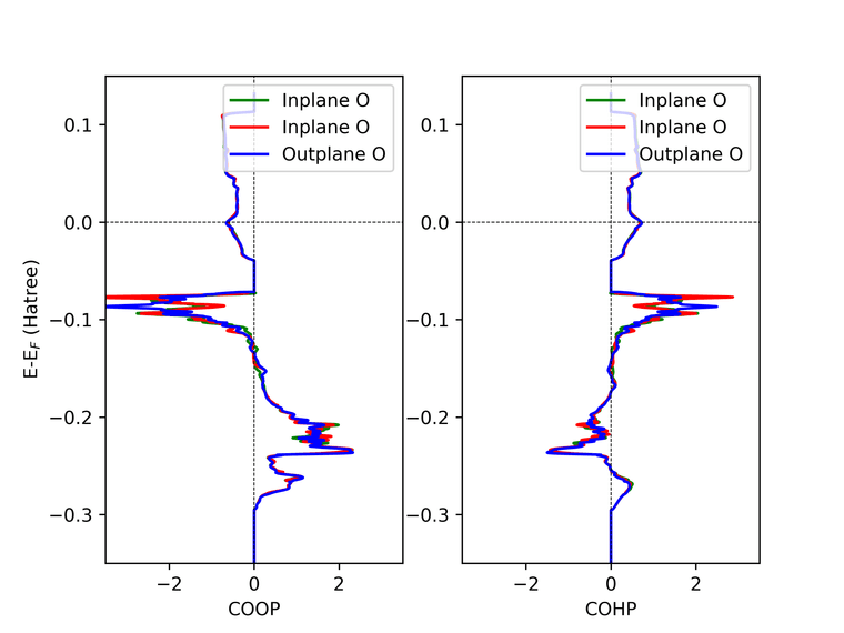
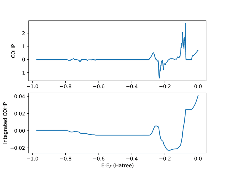
    I am studying a particular Perovskite structure. I performed COHP calculation to understand the bond strength. As per the paper mentioned in the manual (PCCP,17,31023-31029 (2015) -"Integration of the COHP diagram is a measure of bond strength (in units of energy)).

    But when I perform the COHP analysis and integrated till Fermi level, I am getting a positive value for the integrated COHP, that means the bond is unstable right ?, which is not possible since it is a very well experimentally observed structure. Attached below are the COHP and integrated COHP plot between oxygen and Ni atom within the considered unit cell.

    COOP_COHP_Plot.png Integrated_COHP_Plot.png

    Any suggestions ? I am attaching the input and COHP files from properties calculation.

    Thanks in advance for your help !

    COHP.dat
    INPUT.d3

    Regards,
    Rams


    Hi Prof. Erba, Thanks for the reply. From the file, I could see there are value from energy " -7.9324E-01" (Line No: 81826). I could plot the data using Python, Xmgrace. With CRYSPLOT somehow the data loading is slow and my browser hangs so I am not able to check it. But definitely there is data. I requested for COHP between Ni and three nearby oxygen. In the file there are 5 columns, so if I am not mistaken it corresponds to "Energy - Next three columns in the order I request - Final Column of DOS ?" (Because the last column data when plotted matches the DOS) Thanks & Regards, Rams
  • jquertin

    Hi,

    I'm currently running some molecular calculation as tests before going to periodic one of porphyrin with Co2+.
    I'm using spin DFT with a spinloc2 1 -5 setting (with HSEsol).
    With POB-DZVP, the calculation finishes successfully while with rev2 it fails after the 4th SCF cycle (sometimes the 3rd) with the good old "NaN at SCF".
    I'm not sure what to try beside giving it more memory (which gives the same results) as those are my first calculation with metals.

    I'm not sure if it's even a bug but since POB-DZVP works and not POB-DZVP-REV2, I figure that there's something that I cannot control at play.

    Best,
    Jean

    PS: I also tried with FMIXING 60, spinlock instead of spinloc2, tighter tolinteg but got the same problem.

    por_co-opt-pob_dzvp_rev2.d12 por_co-opt-pob_dzvp_rev2.out


    Hi, @jquertin said in SCF fails spinlock with POB-DZVP-REV2: In the case of SPINLOCK, the manual clearly explain that the NSPIN value is the difference in number of alpha and beta electrons. For SPINLOC2, the text only refers to the spin while the table gives the same definition for SPIN as for NSPIN (in SPINLOCK). The argument SPIN of SPINLOC2 still represents a number of electrons, as in SPINLOCK. @jquertin said in SCF fails spinlock with POB-DZVP-REV2: Furthermore, in the calculation, if using SPINLOC2 with 6 or 6.0 as the spin (as defined in the table), crystal defaults to SPINLOCK. That's right. SPINLOC2 requires a non integer argument. For integer arguments it reduces to SPINLOCK. @jquertin said in SCF fails spinlock with POB-DZVP-REV2: In short, if I define SPINLOC2 SPIN as 3 (1/2 * 6) or 3.0, crystal defaults to SPINLOCK with NSPIN 3 which is actually half of what I want. In both SPINLOCK and SPINLOC2, the argument is meant as a number of electrons. Thus, if you have 6 extra up electrons with respect to down electrons, the input value should be 6, not 3. For integer values, SPINLOC2 is of no use. Hope this clarifies things a little,
  • Drmajouri2025

    I'm working on electron density maps using CRYSPLOT and I’m trying to generate contour plots in different planes—specifically XY, XZ, and a custom diagonal like XY-Z. I’ve successfully used RECTANGU for XZ plots, but I’m not sure how to define the input for other orientations.
    Here’s a simplified version of my current input:

    ECHG
    0
    50
    ATOMS
    1 0 0 0
    2 0 0 0
    2 0 0 1
    RECTANGU
    MARGINS
    3 3 3 3
    END
    END
    

    How can I modify this to get a plot in the XY and XY-Z plane and if 2 atoms are in the same cell as 0 0 0, they overlap or no? *


    Thank you, Dr. Alessandro Erba, for the helpful suggestion regarding the use of the COORDINA option. Your example for defining the XY plane was clear and easy to follow — I’ll definitely apply this approach in my setup. Thanks again for your guidance! Cheers